Those were activation two weeks apart and not tests per se but an effort to find if any meaningful improvements in signal reports are realizable. I was just curious to find out if such a comparison is meaningful. I will still do the activation since that is what SOTA activators do which is to activate. If the results are not seen to be meaningful then I will not report it and just keep the results to myself.
Thanks Ariel for sharing the results of the WSPR test carried out on 20 m.
I would actually have expected that the graphs for the two test objects would more or less shake hands over the entire duration of the test.
Therefore I suspect at the moment that an unknown player could be responsible for the indentation in the red graph. In order to confirm or rule this out, the test would probably have to be carried out twice on exactly the same antenna locations with interchanged test objects.
I would also be very interested in WSPR test results on 80 or 60 m. The test results from the 2 different bands could then on the one hand be checked for agreement with the calculated values and, on the other hand, contribute to a more well-founded assessment of the examined test objects from a point of view of radio practice.
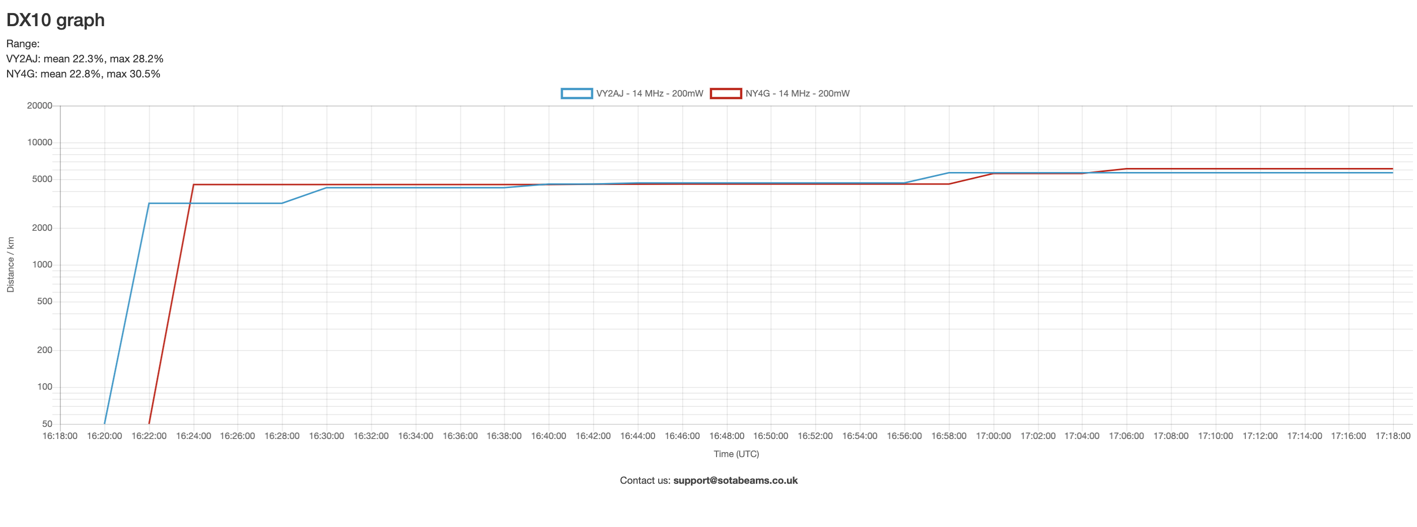
Here are the results of the repeat WSPR head-to-head transmissions on 20 meters. The initial head-to-head test was run yesterday and reported on further up in this thread.
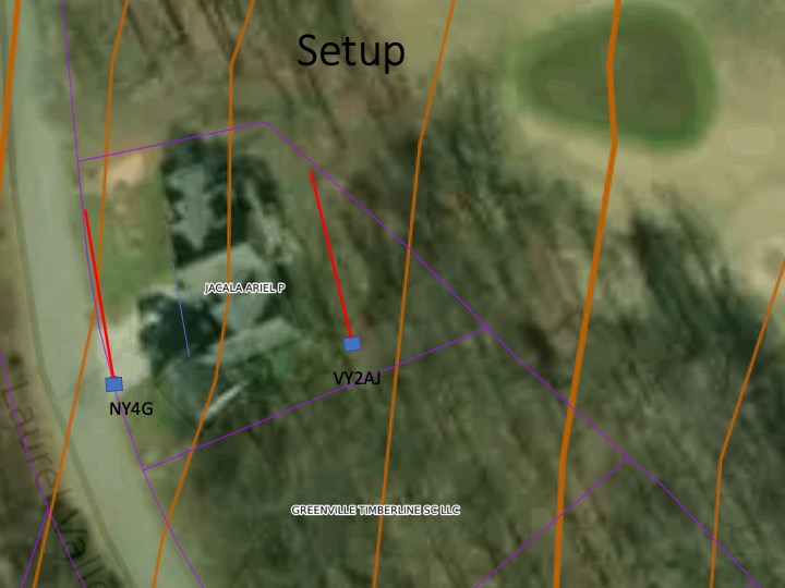
The setup is as shown in the image below. The two antennas are arranged as inverted Vee in the same azimuthal orientation with the feedpoint on the south side denoted by the blue boxes. The image shows 10 foot topographic contours and also shows the global imagery to show both the presence of roads and vegetation. The two antennas are separated by about 75 feet of space. The NY4G coupler has the 2 turns primary with the crossover and bifilar winding of the primary. The VY2AJ coupler has the 3 turns primary with a tap instead of the bifilar winding and the turns are wound tightly together with no crossover. Both transmitters are identical 200 milliwatts WSPRlite programmed with their respective call signs. The NY4G and VY2AJ positions were swapped from yesterday. The image shows the positions for today’s comparison. The only variables are the couplers and the relative position of the antennas with each other. They both see the same propagation conditions.
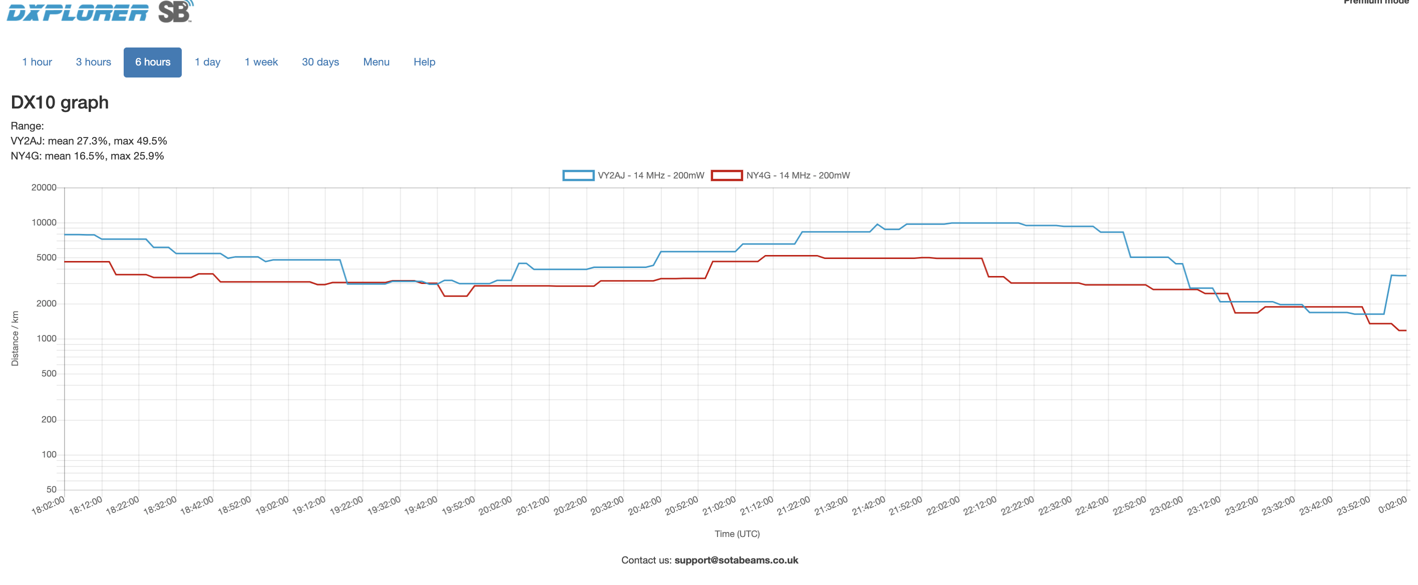
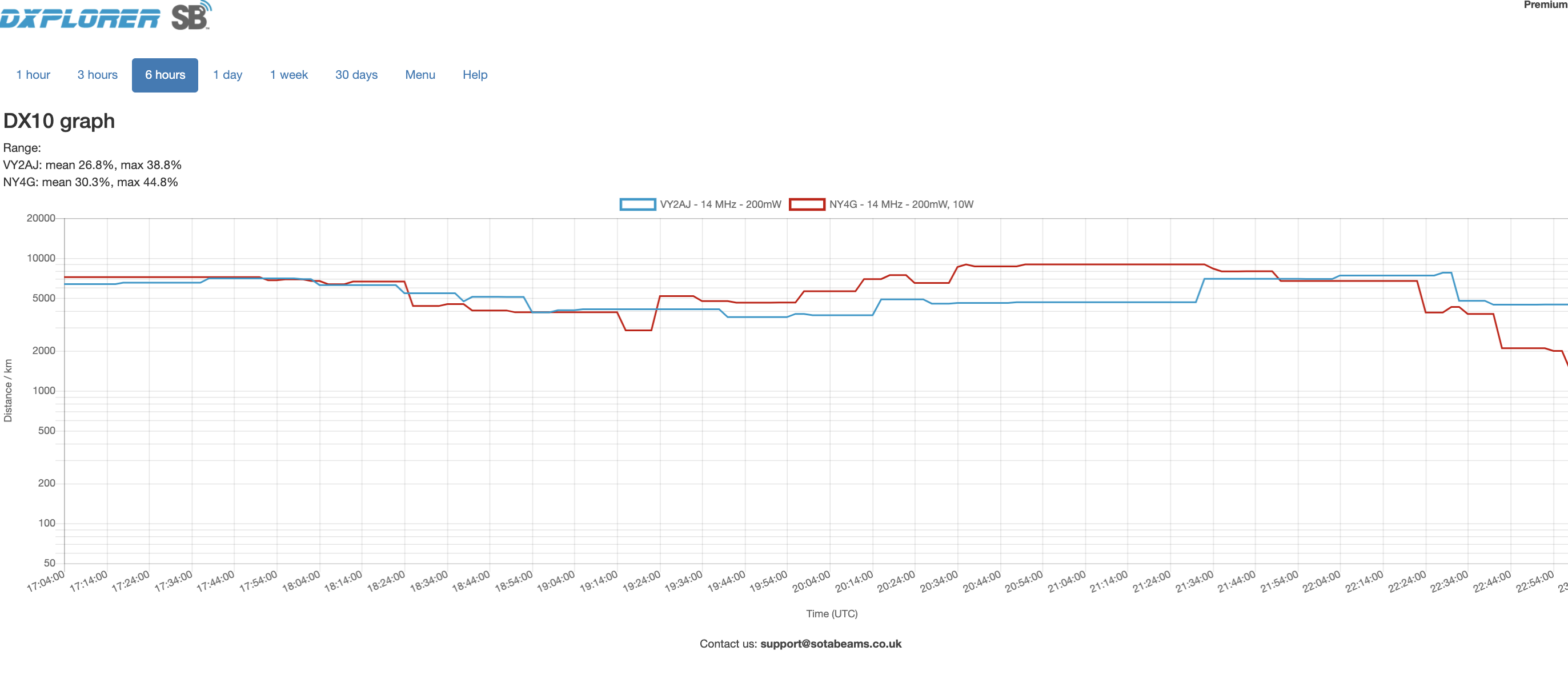
The blue trace being VY2AJ and the red trace NY4G. Similar to yesterday, VY2AJ outdistanced NY4G. Today by quite a bit more than yesterday - the Y axis being a logarithmic scale on average by almost a factor of 2:1. The position of the VY2AJ appears to have some sort of additional advantage (in addition to the more efficient coupler/transformer) - perhaps better ground conductivity or some other reason. The advantage of VY2AJ is perhaps the composite from yesterday and today.
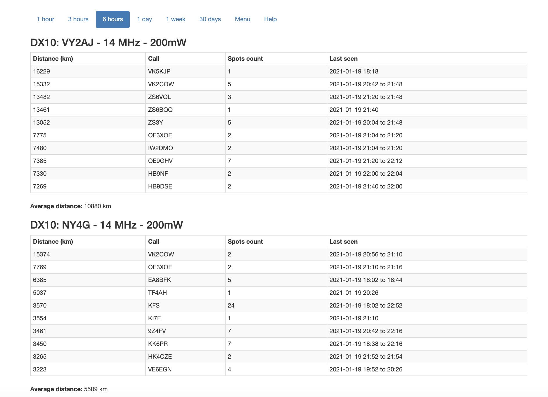
As only vk2cow reported both signals, almost no comparison is possible between these data sets. I notice vk2cow managed to be about 42 km further away in one data set. How is that possible? I know Dimitris VK2COW as he lives about 20 km away from my home location. I doubt if he was operating two different receiving stations.
So what do these two data sets mean? I’m confused.
Thanks Ariel for running the WSPR test again with the couplers swapped and for the now detailed test documentation, I appreciate that. The only thing I may have overlooked is the antenna length used (1 or 2 half waves?).
When looking at the 2 recorded graphs, the discontinuous course is again noticeable. So the unknown player still seems to be fooling us and even after the 2nd test we cannot see that the difference of approximately 1 dB in the transmit power delivered to the antenna is clearly confirmed by the RBN spots.
As mentioned in the email from yesterday, a possible player could also be the effect of the antenna setup, especially with antennas that are opposite/parallel to each other.
With the distance of approx. 75 feet (about 1 lambda) specified in the test documentation, the following 2 effects are conceivable:
Antenna diversity gain (spatial diversity in our case), possibly a little more pronounced due to the sloping terrain. However, that would hardly explain the discontinuous course
Additional gain by antenna separation at a certain distance to use the neighboring antenna radiator as a reflector. That could be very well an explanation for the discontinuous course.
When looking at the skimmers listed for the two antennas, it is noticeable that some of them come from very different regions.
This would support the above thesis that the two antennas could radiate in the opposite direction due to the influence of a reflector. As a result, one antenna would point in the direction of sunrise and the other in the direction of sunset. Therefore it is conceivable that e.g. VK2COW could have received from one antenna on the long path and from the other on the short path.
The simplest solution for creating clarity in this coupler test using WSPR would be to carry out the test again with identical couplers (no matter which variant) for both antennas and possibly with exactly the same antenna setup.
Sorry Ariel, that would also make it clear that the key to solving this phenomenon (unfortunately) can only lie with you.
Andy, your insecurity doesn’t seem to be so unfounded.
A quick look with EZNEC confirms that a reflector also has an influence at a distance of ~ 1 lambda (22 m), albeit significantly less than at ~ 1/2 lambda (11 m) or ideally at ~ 1/4 lambda (5.5 m).
BUT all this only if the reflector is approx. 4% longer than the radiator … which in our case, at least not at first glance, is not the case.
Therefore I should better not call the cause of this phenomenon a reflector for the time being, but only as a symptom as we know it when it is caused by a reflector.
However, this does not change the further procedure suggested above.
BTW, a somewhat larger map section of the test site (broadside to the antennas) would be helpful for assessing the antenna radiation properties.
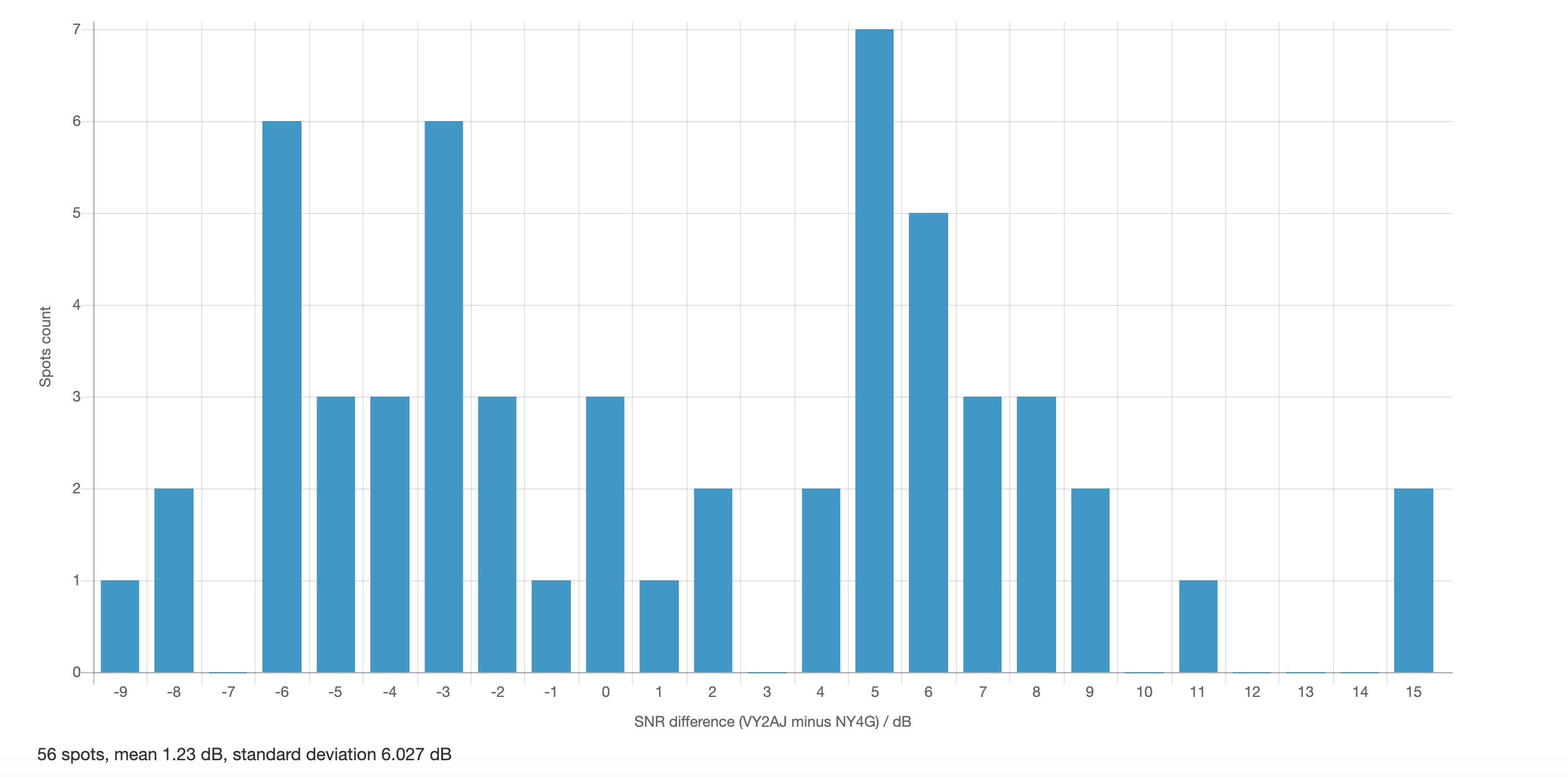
As I understand it, this reports the number of spots with a specific station within the specified period - in this case 6 hours) and then takes the average of the difference (VY2AJ-NY4G) in SNR for those spots.
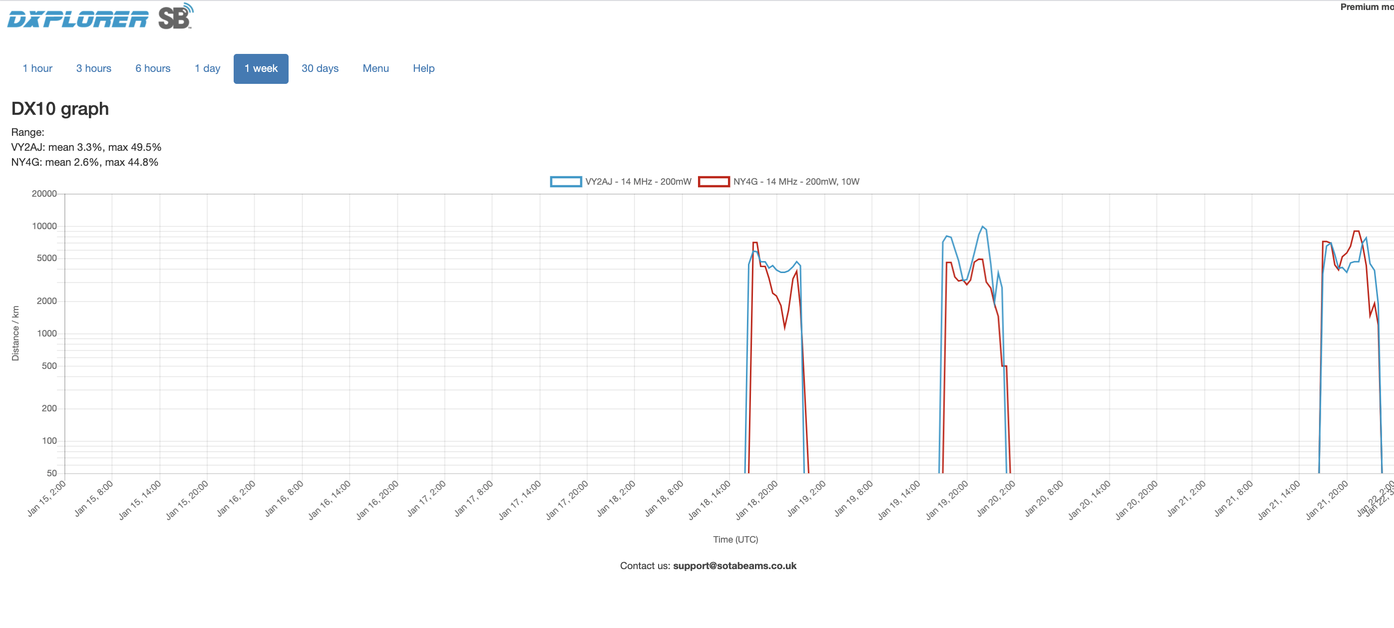
I have done the “control” experiment suggested by Heinz HB9BCB in an attempt to isolate the effect of the “third player” other than the two couplers. It was noticed from Jan 18 and 19 that there appears to be an advantage with the position on the lower part of the slope. The recommendation by Heinz was to run a third test using identical couplers from both positions. Below is the 6 Hour DX10 chart.
The distance starts out together and then start to diverge at 1800 UTC (Sunset at GMT). The nightime propagation at the receiving stations influence this result. Then another divergence happens at starting at 20:00 UTC highlighting the advantaged position of the antenna lower in the slope (red trace). The DX10 Table summary for the 6 hour period indicates that the lower position has an 800 km advantage over the higher position.
NY4G is at this lower position. If one deducts the 800 km advantage from the previous two days results to sort of “equalize” matters from the “advantaged position” then
the average distance for Day 1 - reported by DX10 Table with adjustment
Coupler 1 VY2AJ (3 turn primary) - 5649 km Position 1
Coupler 2 NY4G (2 turn primary) -4751 km Position 2
the average distance for Day 2 - with adjustment
Coupler 1 VY2AJ (3 turn primary) - 10080 km Position 2
Coupler 2 NY4G (2 turn primary) -5509 km Position 1
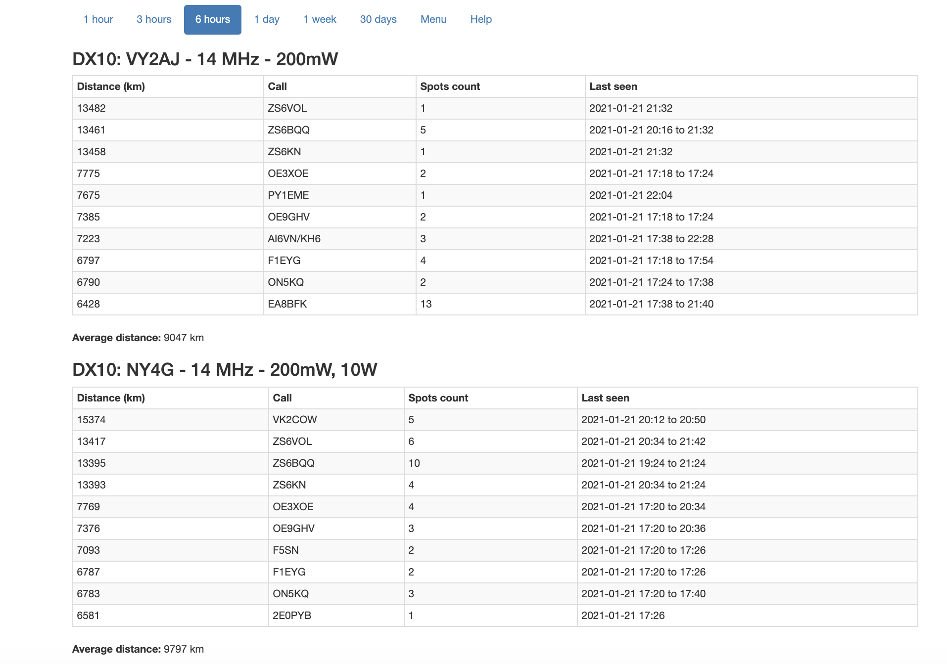
the average distance for Day 3 - data reported by DXeplorer
Coupler 1 VY2AJ (3 turn primary) - 9047 km Position 1
Coupler 2 NY4G (3 turn primary) -9797 km Position 2
This suggests that the advantage of the more efficient coupler in terms of distance ratio is somewhere between 20% points to 80% points better.
Ariel, I am pleased to see that your great persistence and curiosity to critically question the first test result and the conclusions drawn from it has paid off. Well done.
Please don’t be disappointed if I still make a small reservation. The radiation characteristic of your antenna is a bit special on the bands of 20-10 m and therefore no longer corresponds to that usually expected from a dipole.
Such a radiation characteristic is typical for all half-wave antennas whose relative height above the ground is low and whose relative antenna length is large (number of half-waves).
That’s why the short masts that SOTA enthusiasts like to use for practical reasons and half-wave antennas are not per se an optimal solution in terms of radiation properties.
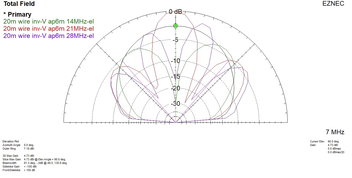
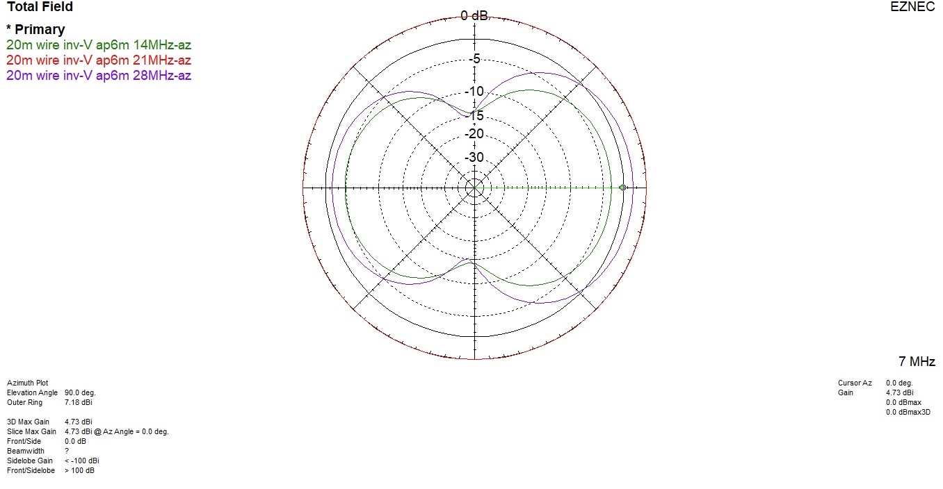
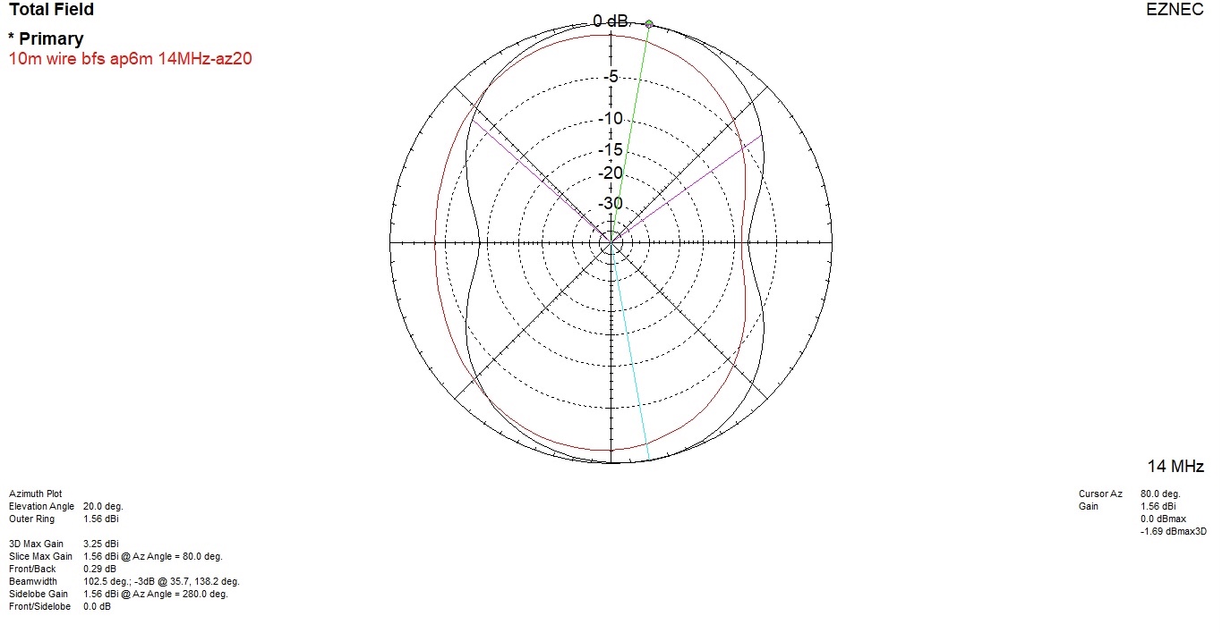
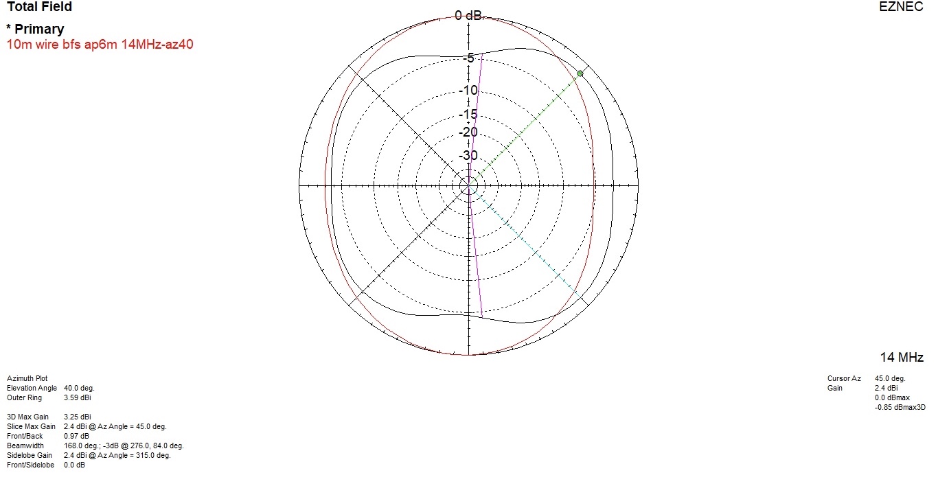
The radiation plots below show the radiation characteristics on 40/20/15/10 m of the SOTA centric EFHW with an apex height of 6 m and an apex angle of 130 degrees.
It is obvious that on 14 and 28 MHz this antenna does not radiate, as is generally expected, all around or on the broad side, but along its length.
This is why the unknown player during the WSPR test on 14 MHz could eventually also be hidden here and not only in the antenna separation in the sloping test area, hi.
The different radiation characteristics of such a multi-band antenna cannot simply “tuned away” with an impedance matcher (VSWR), no matter how ingenious it is.
Or in other words: In any case, it is advisable to look at the entire system and not start with the gold plating at one end if it is rusting away at the other end …
Instead, an attempt must be made to reduce the relative antenna length and thus the number of multiples of half waves.
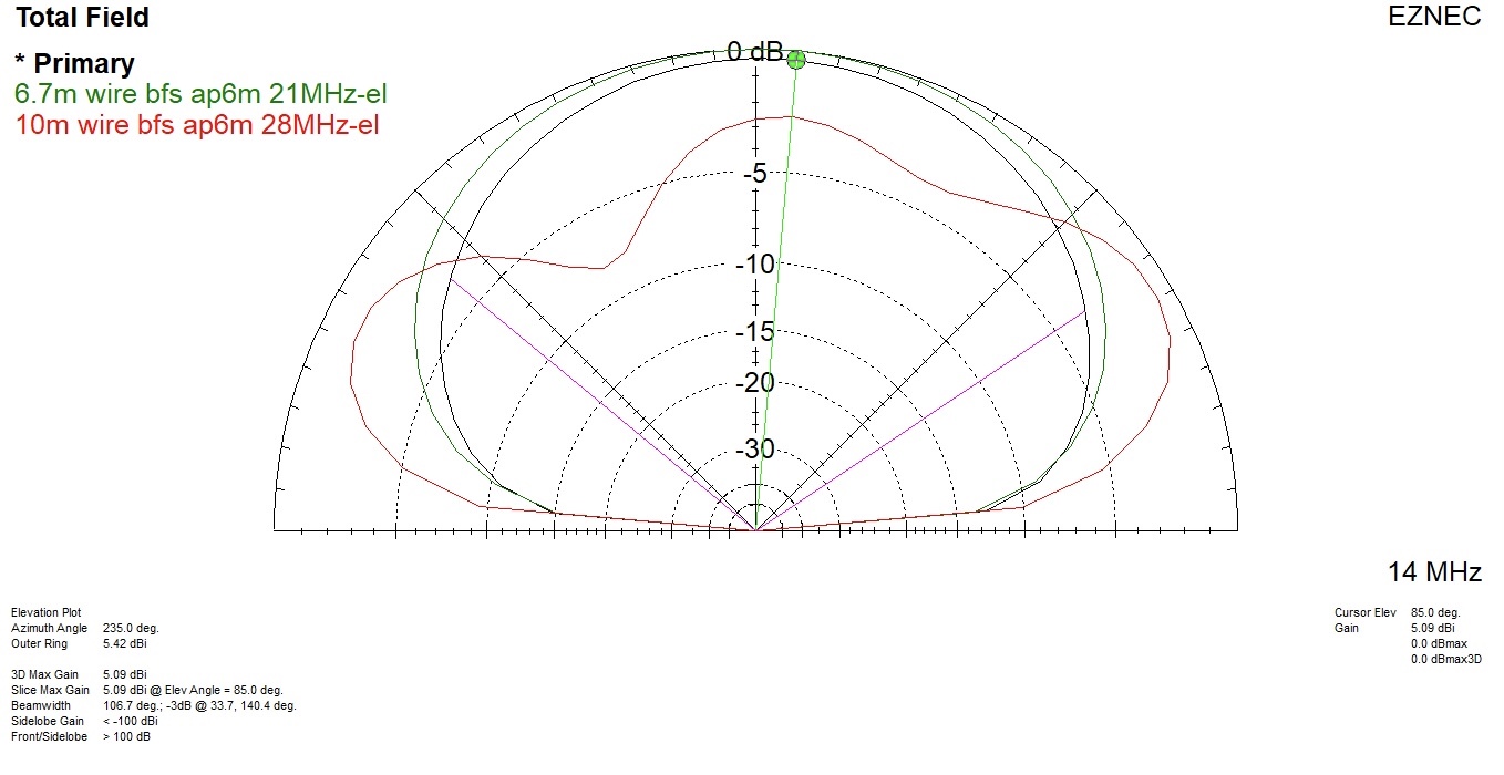
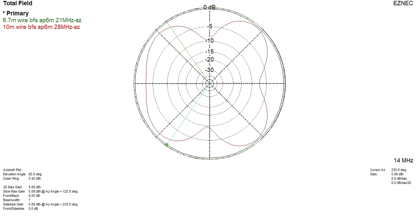
One possible solution could be (radiation plots below)
improvement on 14 and 28 MHz: an additional link for an EFHW on 14 MHz and use of this antenna length also for 28 MHz (2x 1/2 lambda). This would result in a base fed sloper (bfs).
improvement on 21 MHz: only possible with an additional link for an EFHW on 21 MHz (resulting also in a base fed sloper)
Thank you Ariel for doing all these experiments and providing us your data and conclusions!
As we see, it’s really difficult to compare two antennas or couplers exactly, even when using two concurrent WSPR transmitters.
There are simply too many error sources that can influence the outcoming result, but I think it’s good enough for our purpose.
@HB9BCB As you state correctly, in general, for a more flat and uniform radiation pattern it’s better to strive for a 1/2 lambda long EFHW wire, instead of using multiple half wave lengths.
But instead of setting up the antenna as inverted-V one can mostly improve the pattern until about the 2nd or 3rd harmonics by employing an inverted-L configuration. By doing so, one even needs less horizontal space.
Without running a modeling software, one can compare the patterns on several harmonics between (albeit for a 40m long wire, corresponding to an EFHW antenna for the fundamental 80 meter band):
I agree with you here Stephan - hard to come to any hard conclusions because so many variable are involved. Just for “grins and giggles” I ran a short head to head WSPRlite test between identical couplers but one antenna radiating two half waves on 20m and the other a half wave sloper from the same inverted Vee (a trap at the 20m halfwave point). Here are the results just before the hour.
Below for information the radiation plots of the 2 compared antennas (az slices at el20 and el40 deg).
BTW, The statistics “Average of the 10 most distant receiving stations” are interesting, but do not paint a complete picture. For example, a statistic “Distance vs average SNR” taking into account all spots caused by an antenna would be also of interest.
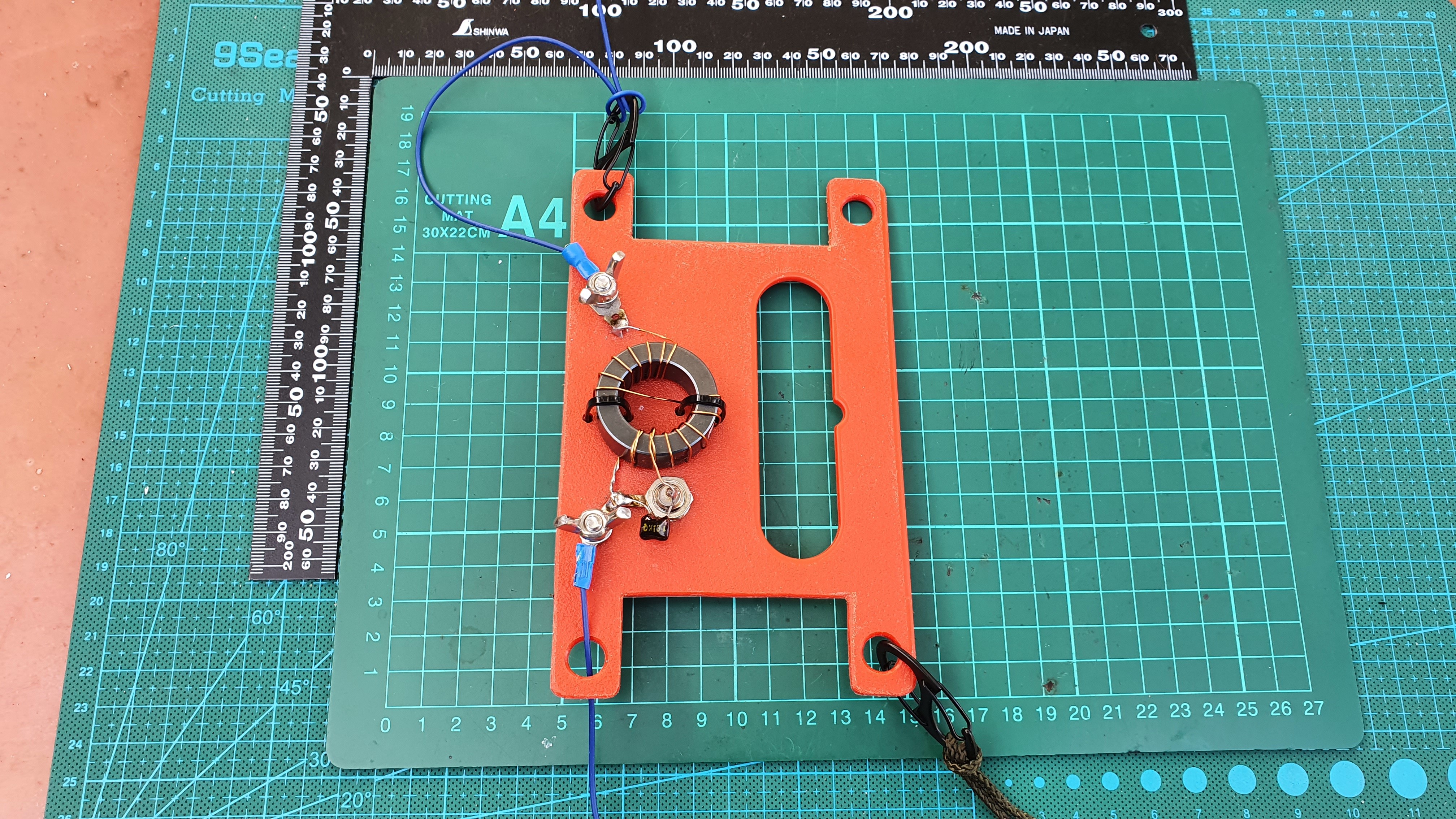
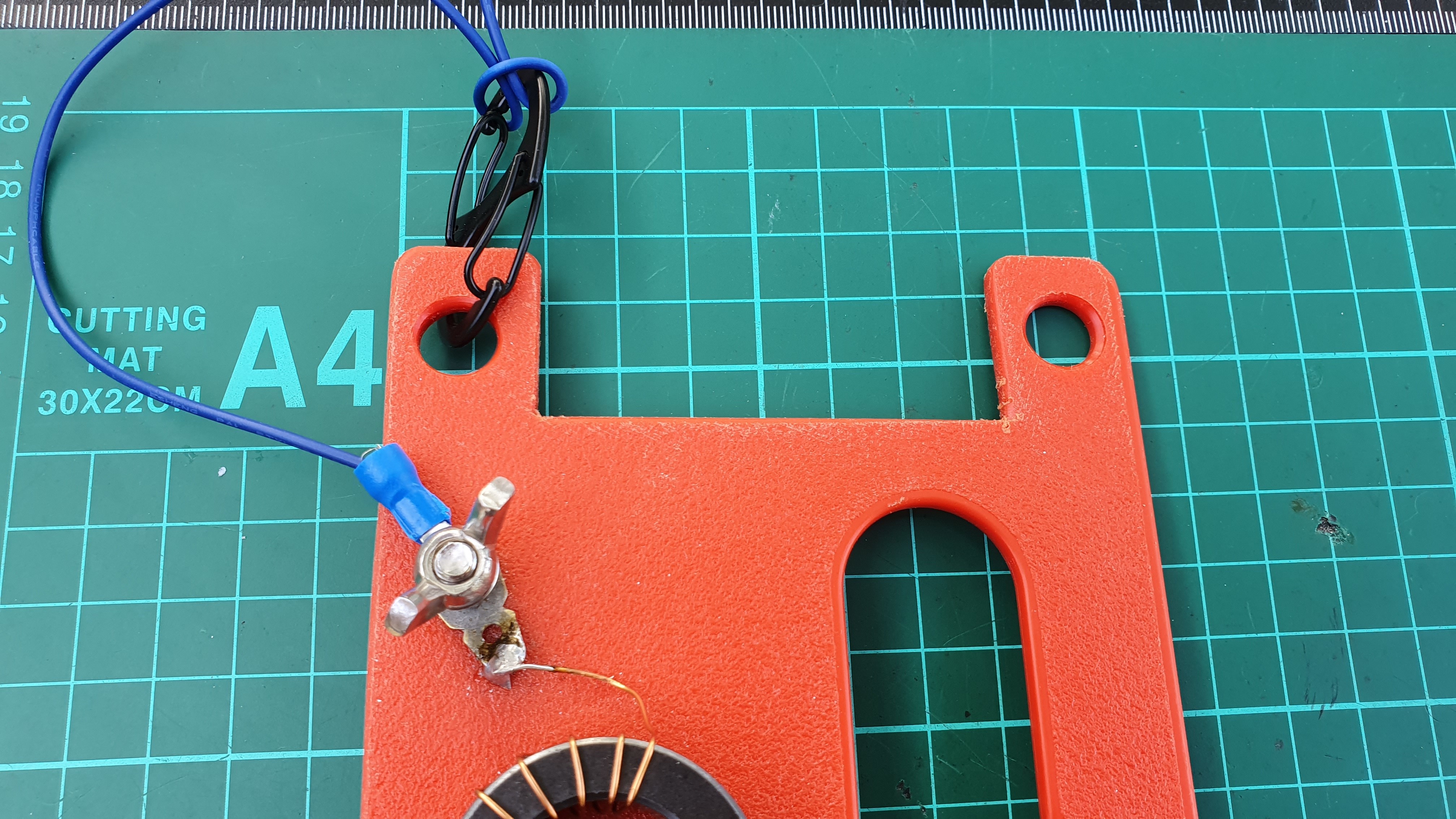
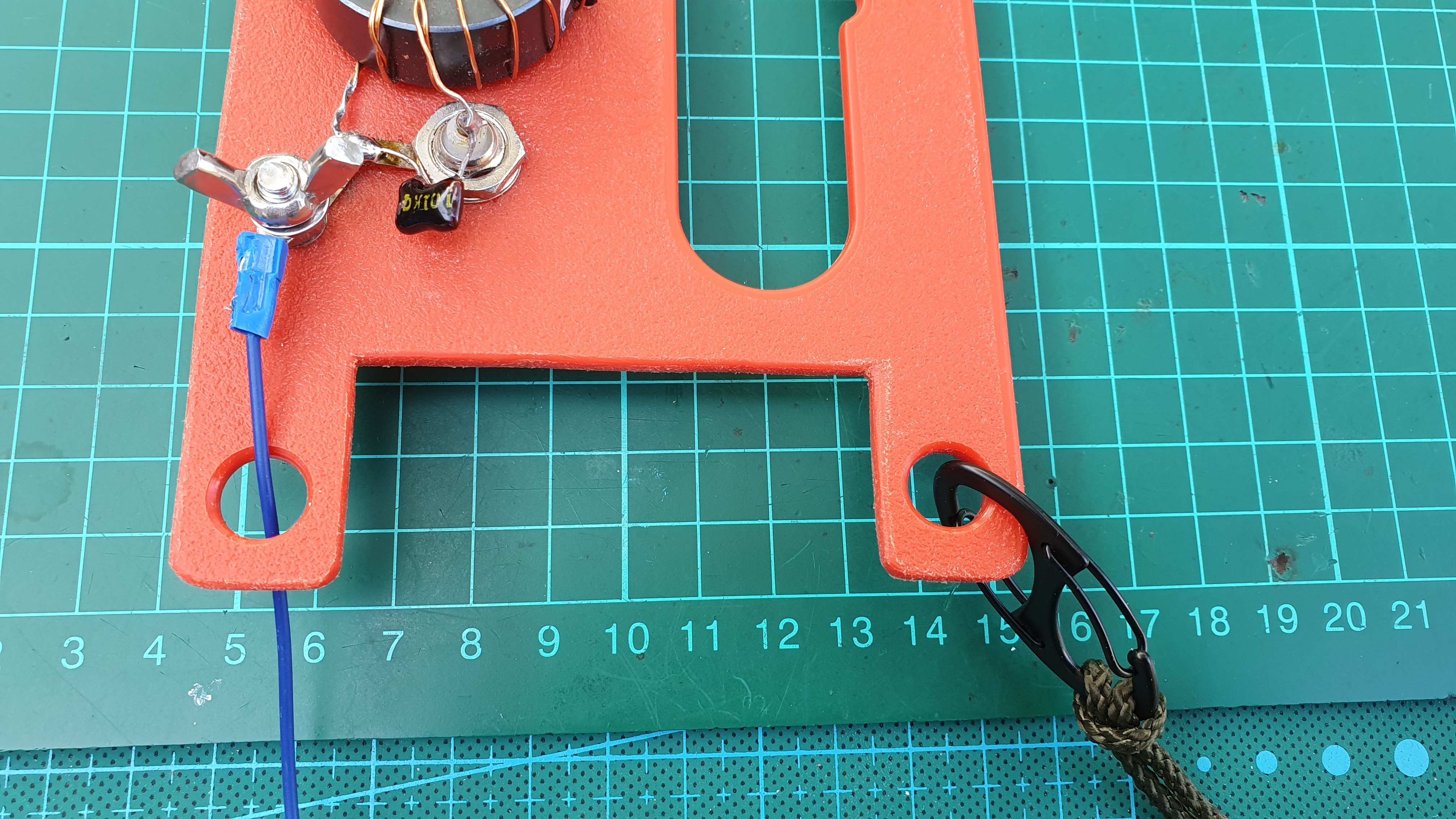
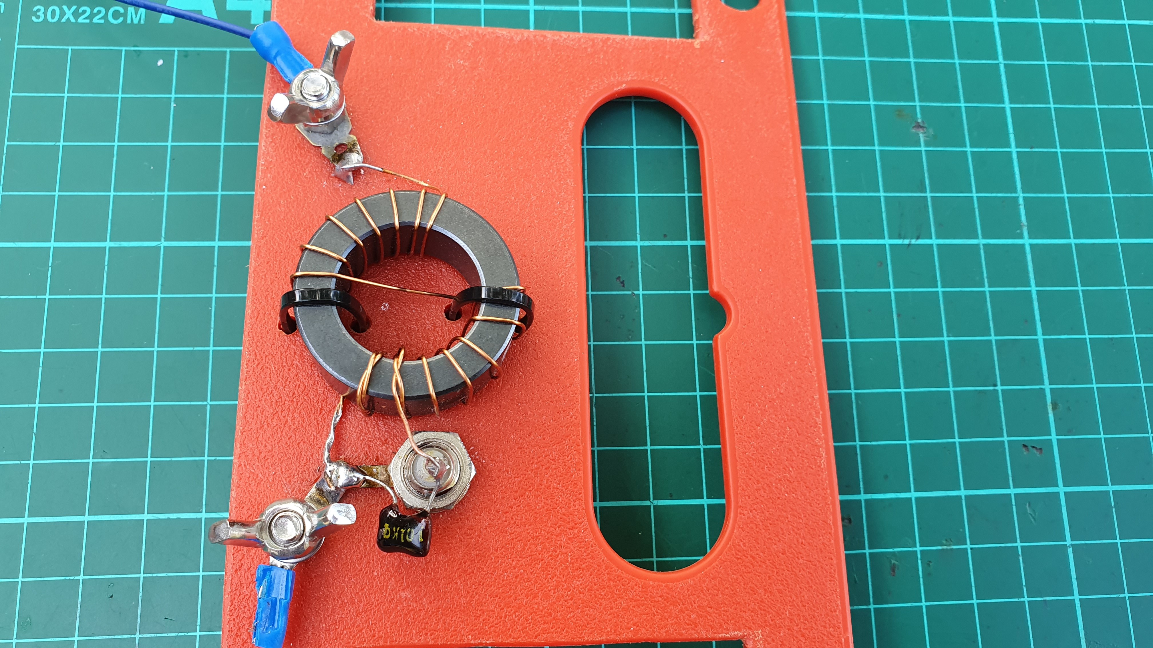
Homebrew 49:1 EFHW using a FT140-43 core, 100 pf mica cap and 19.8 metres of wire. To help reduce RF on the coax feedline shield, I use a 6.8 metre counterpoise. Insulator is 3mm kitchen cutting board purchased from a mainstream supermarket. Cost for materials is $20.00 or you can pay $50+ postage at popular commercial sites.
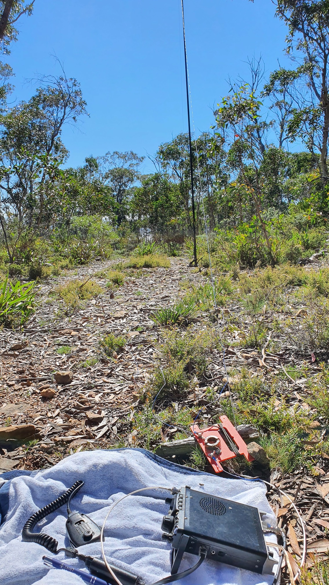
Yesterday from VK2/ST-001 I worked VK2 and VK3 on 40m and VK1, VK4, VK5 and ZL stations, including two ZL S2S, on 20m all at 5 watts SSB. ZL path is ~2300 km.