A SOTA Centric End Fed Half Wave Antenna (Part 1)

Heinz, you are correct in that a half a watt only amounts to less than 1 dB (or 1/6th of an S unit) which really can’t be heard. My calculated VSWR losses are quite small when the antenna is tuned. The cable losses are not an issue for me - just trying to account for every source of loss in my calculations.

Ariel NY4G

Heinz

Those are very nice looking couplers. Would it be possible to obtain one from you?

Please reach out to me at ny4g@hotmail.com

Ariel NY4G

Mike, typically use 10 feet of RG174 and that is what I use to test the antenna.

Ariel NY4G

1 Like

Hi Heinz.
Thanks for his contributions. They are very useful.
Please tell me where to buy the Fair-Rite toroidal core 2643625002 and 2643626302.

73 de Dani EA5M

mouser.co.uk have them at £0.46 each. or £0.37 each for 10.

The downside is unless your order is more than £33.00 there is a £12 postage charge. Maybe a few people could combine an order.

1 Like

Ok Stephan, my project to improve the EFHW couplers used so far (in the slim design) lasted from spring 2018 to autumn 2019, that was a little longer than expected (…).

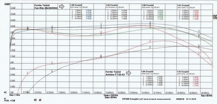
For this purpose, after a prior evaluation using the toroidal core calculator from Owen Duffy, prototype couplers 1:49, 1:64, 1:69, 1:81 were built, measured on the workbench on purely resistive loads and back-to-back and finally tested on real EFHW antennas for 80-10 m. The following ferrite cores were considered:

  • Amidon 2x FT-82-43, FT-140-43
  • Fair-Rite 2643625002, 2643626302, 2643801202 (comparable to FT-114A-43)

During the measurements with the VNA SDR-Kits v3, the values ​​calculated by the toroid calculator have been confirmed quite well, taking into account the large tolerance of the AL value of the ferrite mix.

Core selection
Because at the time I was obsessed with the idea of ​​building the most efficient coupler possible, I chose the smallest Fair-Rite core 2643625002, which seems to be just sufficient for a load of max. 15 W cw/ssb and 10 W data.

Sticking points
Somewhat unexpectedly, some sticking points emerged during construction:

Point 1
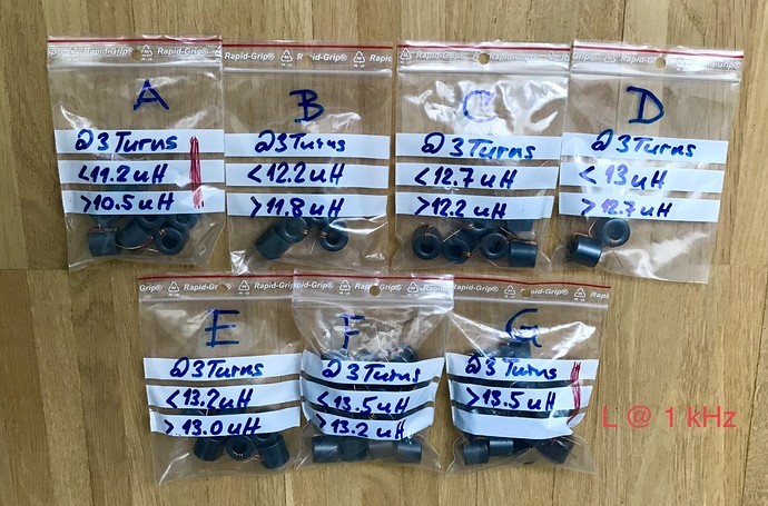
With the 20 toroidal cores from the 1st batch, it was not possible to build 1 pair of 1:49, 1:64 and 1:81 couplers each with almost identical electrical properties.
Reason: The AL value of the #43 ferrite mix varies by approx. 26% with this toroidal core (arithmetic mean of AL(1 kHz) = 1.344 uH/1 turn).

With 20 toroidal cores from a 2nd batch (from another supplier) this goal could just be achieved.
Another batch of 30 cores was then required in order to be able to build some couplers for my SOTA colleagues (…).

Point 2
The reasonably accurate reproducibility of a coupler was extremely difficult. This is not only due to the large tolerance of the mentioned AL value, but also to the fact that the coupler is very sensitive to stray capacitance. For example, unevenly spread “primary windings” had a strong effect on the electrical coupler properties.
Therefore, all turns were not only attached tightly, but then pushed together completely. That was almost a watchmaking job, hi.

Point 3
The aforementioned sensitivity to stray capacitance was also noticeable when it was installed in an (adequately small) housing. The stray capacitance due to the proximity to the housing material and, above all, to the material attached to fix the core also tugged a bit on the previously nice-looking graph curves.

Final tests and conclusion
The final tests with EFHW antennas for 80-10 m then only confirmed the well-known: Due to the complex and non-linear permeability of the ferrite material and the non-constant impedance of the EFHW antennas in the range of 80-10 m, which unfortunately do not neutralize each other, result mismatch losses.

These mismatch losses occur with the following tendency: Below approx. 10 MHz with a decreasing coupling ratio and above approx. 20 MHz with an increasing coupling ratio.

A 1:64 coupler is therefore best suited as a universal coupler for the entire frequency range, a 1:81 coupler for the range of approx. 80-15 m and a 1:49coupler for the range of approx. 30-10 m.

The 1:49 couplers are particularly popular with QRO enthusiasts because of their low transmission loss (-> heating), unimpressed by the high mismatch losses below approx. 10 MHz (…).

As the attached overview with the S21 graphs (of operational couplers) suggests, the project was successfully completed.

Would I choose the same toroidal core again? If at all I would probably use a slightly larger toroid.

73, Heinz
6 Likes

Heinz,

Thanks a lot for your detailed explanations! It seems you spent a lot of time by digging into this topic. I’m also still looking for the perfect antenna system, that, as we all know, does not exist, hi. But like you, I wanted to dig deeper and try different things.

So you had to find cores with similar AL, which is a tedious job. This variation might be the reason, why I also measured different values with similar couplers. I just ordered a batch of 10 pieces from mouser, along with a selection of silver-micas.

But the variation of the material is only one part of the story. On most activations, I took an antenna analyzer with me and measured the antenna system, since I was mainly interested in the real field measurements and results. I always used the same reference coupler and tried to set up the antenna in the same way, but as you may guess, this is not always 100% possible.
The variation of each summit (antenna impedance, resonance and minimum resulting VSWR) was sometimes quite large, probably with a bigger variation than you measured with the different toroids (just guessing).

Your findings about the optimal winding ratios and therefore antenna impedances are pretty consistent with my findings. In general I got better results above 15m with a 1:49 or even a 1:36 coupler, below 40m, the 1:64 or further down the 1:81 was superior. This of course changes with height above ground and wire diameter, just to name a few attributes. I had to realize that the so called broadband coupler is not that broadband as I thought it is, but I really like the easy and quick setup of an EFHW, without the need to tune and my 818 never complained when the match was not perfect (SWR < 2). I even made it once work on 160m.

One question though: In your final conclusion, you state that you would choose a slightly larger toroid (e.g. the 2643626302?). Is this because you want to run with more power, or is there another reason?

Thanks again for your interesting findings!

73 Stephan

1 Like

No, not at all, on the contrary, hi.

I already know that “If at all” and “slightly larger” are a bit vague, but that was deliberately chosen.

Re If at all:
To be a bit more specific, at the moment I simply see neither a need nor a reason why I should deal with this topic again.

Re slightly larger:
No, the size difference to the 2643626302 core would be too small, from the point of view and to protect my aging fingers (…). So that would probably be the Fair-Rite 2643801202 or the FT-140-43 core.

Thanks Heinz for your explanations, I understand.

The 2643625002 toroid has indeed not so much space for many windings, but when using CuL with 0.63mm diameter, one can still wind 1:81 ratios, accounting for a total of 27 windings (3:24).

73 Stephan

Yes Andy, and upwards the duty-free limit applicable in a country can be the spoilsport :upside_down_face:

costs for customs declaration CHF 17.45 Detailed information on Swiss Post prices
Swiss Post costs for opening the consignment CHF 13.00 The sender did not provide sufficient details on the contents of the parcel, which is why the Swiss Post had to open it for clearance

The upper limit of the goods value (incl. transport costs) for an import exempt from VAT is:

  • 7.7% VAT (applicable to majority of all consignments) => CHF 65.00
1 Like

There is no duty free limit in the UK any more, part of the VAT changes that comes to the remaining EU27 (EFTA too I think) in July 2021 has started in the UK this January. i.e. the Vat free limit of £15 has gone and any overseas vendor is required to add VAT for orders under £135 (150EU). Above £135, the duty and any import tax UK have to pay will be collected by the Post Office/Delivery companies handling the import along with their harge for collecting the duites.

UK purchasers can see this now when they buy from outside the UK on eBay where eBay adds the VAT onto orders from China say.

The wire diameter I used for this Fair-Rite 2643625002 core (-> max. Reasonable HF power), taking Owen Duffy’s findings into account, is 0.5 mm (# 24). The turns should lie next to each other on the inside of the toroidal core without any space between them, ie both the “evenly spaced” method used for oscillating coils and the “cross-wound” method propagated by Joe Reisert for winding chokes with coaxial cables do not result in any improvement, but only increase the flux leakage.

Appropriate wire diameters usually used
up to 0.50" cores: 0.4 mm (#26) or 0.5 mm (#24)
up to 1.14" cores: 0.63 mm (#22)
up to 1.40" cores: 0.7 mm (#21) or 0.8 mm (#20)
up to 2.40" cores: 0.8 mm (#20) or larger

1 Like

I completely agree with you, even most of the commercial products and most of the web source say the opposite.
The same applies to the primary bifilar windings with which I could not measure any improvement, therefore I simply tap the winding.

To me it seems it’s like with the spinach myth, that you sometimes still hear, even more than 100 years after the decimal point error was found :thinking:

73 Stephan

Ok Re both Stephan, but I still loved the Popeye movies very much, or maybe because of that, hi.

1 Like

Speaking of myths or HAM myths in particular, under the title of this thread one would also have to speak of the 0.05 Lambda “counterpoise” Ham myth, which would probably make the already long thread again as long, hi.

When asked about the simulation of End Fed Antennas by EZNEC, Roy Lewallen confirmed that the algorithms used are based on Maxwell’s findings.
That may be the reason that many EZNEC users cannot simulate an EFHW antenna correctly.

Therfore the section
Building the Model/Some Special Cases/End Fed Antennas, EZNEC User Manual v6

would also be very readable for all non-EZNEC users and especially for those (many) who propagate the “counterpoise length” of >= 0.05 lambda postulated by AA5TB as = 0.05 lambda (exactly/carved in stone 0.05 lambda instead of at least 0.05 lambda).

As can be seen in practice with portable EFHW antennas and moderate transmission powers, in most cases the stray capacitance created by the equipment and the operator and/or a short feeder cable is sufficient to adequately close the open circuit. Such a simple explanation may fully satisfy the practitioner, but not a theoretician.

It is therefore not surprising that Owen Duffy also commented on this point from an expert point of view.

https://owenduffy.net/blog/?p=7984

Edit 14.01.2021
Lately some people propagated to implement the “0.05 lambda counterpoise” by means of the coaxial cable used to feed the EFHW antenna, to insert a common mode choke at a distance of 0.05 lambda from the feed point. The main advantage mentioned: minimal SWR and no more unwanted interference radiation in the shack (?).

Josef Fuchs (Fuchsantenne) did not have to deal with any of these problems of adapting significantly different impedances at the feed point of half-wave antennas in 1927, because the decoupling circuit (tank circuit) of the tube output stage was high-impedance and the desired voltage coupling was automatically achieved.

2 Likes

if wound it 3x8 turns then 24 so it will be 1:64 i have made 2 of them and work it portable with 20mtr wire λ/2 for 40m so i place a link for 30m and i work 40 ,30, 20, 15,10 with Good efficency…73 de SV2HSZ

Mike,

Unfortunately, this notation cannot be understood so clearly for me.
Could you therefore state the number of turns on the primary and secondary side of the impedance transformer?

yes primary 3 secondary 8 turns soon i will upload a photo

Hi Mike,

Thanks for sharing your pictures!

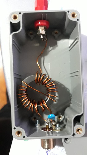
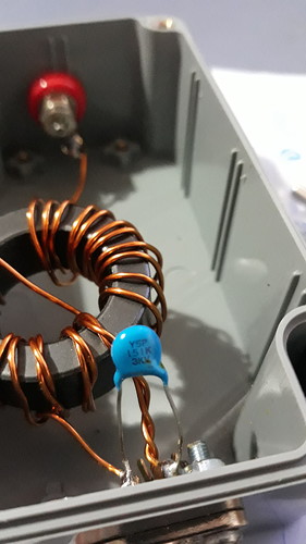
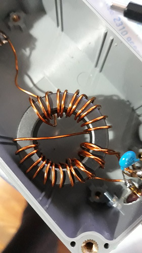
If I counted correctly, to me the ratio is 3 to 24 windings and therefore as you stated about a 1:64 or a 50:3200 Ohm coupler. If you want to improve efficiency, you would have to make the windings tight and use another core toroid geometry or stack two or more of them. Also, the bifilar primary winding is not necessary. I don’t know which material your toroid is made of and don’t know about the quality of the shunt capacitor. It seems it’s a 150pF 3kV one, allowing QRO power levels, since it’s on the primary side, but this doesn’t say anything about it’s quality and if the capacity with your chosen toroid is right (for which frequencies?). Heinz and me compared in this thread some of your ingredients as “spinach myth” :wink:
I recommend you watch some videos that can explain and show several of my above statements much better: Evil Lair Electronics - YouTube

@HB9BCB I also agree with you about the 0.05 lambda counterpoise. It should be in total at least 0.05 lambda long. If no common mode choke is employed on the coax’s coupler side, the coax shield, the rig, other connected cables and the operator form the total counterpoise length, including stray capacitance. When the antenna is resonant, I could not measure any resonance or impedance change by adding more wire as counterpoise (OK, it was already longer than 0.05 lambda).

73 Stephan

3 Likes

thank you for your reply both i use this type over a year from bands 20m 30m 40m for best performance but it tunes and 15m 10m ratio with 3 primary works better for bands 20m and under and ratio with 2 primary turns works better from 20m and over my toroids are FT-140-43 AND FT240-43. But For Sota i use 1:49 with 2 primary and 7 secondary with FT-114-43 With 10mtr wire 20m 10m and one link to 5mtr works to 6mtr tnx 73…