A SOTA Centric End Fed Half Wave Antenna (Part 1)

Thanks for sending the table and helpful suggestions by HB9CB. I will build also a version with 3 turns primary and 21 turns secondary to see if I can improve the efficiency. i will compare the results with the activation I did at W4T/SU-024 on 20m and 60m. SMP provides a graphic of the QSO’s made from that day on 12/29/2020. The results include 3 transatlantic Q’s on 20m and an S2S with WB2FUV on 60m over a 600 mile distance.

Ariel NY4G

1 Like

N4HNH made a YouTube video from the activation he and his brother Wayne W4KWM from North Georgia using the antenna I made for Wayne. They were both running 45 watts using an FT891 and SSB. The video may be found at this link SOTA Expedition to Blue Mountain W4G/NG-010 with the NY4G EFHW antenna - YouTube

The SMP “reach map” for W4WKM on 60m SSB is below

N4HNH operated on 20m also at 45W SSB. Max distance was 2085 miles.

.

Scott KW4JM took this same antenna system I made for him on a three day backpacking adventure on three summits in the North Georgia mountains and yielded 5 DX contacts including one with ZL1BYZ, and 8 S2S’s, and 108 QSOs.

Ariel NY4G

1 Like

Ariel,

I’m very interested in your linked EFHW antenna design. Glad to be part of the experiment.

Regarding our December 29th s2s QSO on 60 M band, I was not in the high peaks of the Catskill Mountains but instead on W2/GC-075 (Spy Rock, elev 443M) in the Hudson Highlands above West Point, NY. My rig was FT-818 at 6 watts. The antenna was an inverted vee 40-30-20 linked dipole up about 20 feet with legs N-S using clip-on pigtails for 60M.

Thanks for the s2s from a lowly 1 pointer on 60M.
73!
Mike, WB2FUV

1 Like

Mike WB2FUV

Thank you for that 60m S2S. That was my first S2S on 60m. It may have been a lowly 1 pointer for you but it was exciting for me to get an s2S on 60m in any form.

Ariel NY4G

2 Likes

At the suggestion of HB9BCB, I built another transformer with 21 turns secondary and 3 turns primary to see if I can realize a small gain in efficiency. I don’t know of an objective way to measure this in reality other than to use the Reverse Beacon Network.

What I did is I used the same antenna wire - but alternated between the two transformers. It is still the same turns ratio but the dips moved around a little bit. I chose 60m for the test 5.332 and 5.373 MHz running 5 watts on an inverted V. On the 14/2 transformer, the sweet spot of the dip was right at 5.332. On the 21/3 transformer the dip has shifted to below 5.332 MHz and I was at 1.9:1 SWR at 5.332. So I will have a little more reflected power and perhaps more feedline losses.

The results of the experiment:

I started out on the 14/2 and 3 RBN stations responded. I QSY to 5.373 and shifted to the 21/3 transformer. The same three stations reported with an improvement from KD7YZ and W3OA-2 and 2 dB worse from K9IMM. This is just 1 data point from two transmissions a few minutes apart.

I checked the rest of the bands and i will have to shorten the antenna and 60m extension to re-optimize for the 21/3. in general, the SWR is lower by a tenth or 2 tenths with the 14/2. But if the efficiency is real i will rather switch to the 21/3. Thanks to HB9BCB for the tip. I computed my radiated power accounting for feedline power losses and it looks like I gained about a 1/2 watt. Once I re-optimize the antenna length, I will have gained 8/10 of a watt.

Ariel NY4G

1 Like

Dear Heinz,

Very detailed and useful table!

Maybe you’re interested to add a Fair-Rite 2643625002 core that I use for my EFHW QRP antenna experiments, since I saw an article from Owen Duffy at Small efficient matching transformer for an EFHW – owenduffy.net and a YouTube video at EFHW antenna - low loss QRP core - YouTube.

With 3 primary windings you’ll get over 90% efficiency (because of its different geometry), which I calculated with the same calculator you used:
toroid-efficiency

Also, your coupler design, that I found in this forum, inspired me a lot!

I’m creating a document with all my ideas and results for a unique EFHW antenna design that I never saw before (7 Bands, including 60m with 20m wire length), inspired from many sources, which I want to share with the community. Unfortunately, some data is still missing and things need more time than predicted…

73 Stephan

1 Like

Ariel,
Great discussion! One item not mentioned above: What is your type of feedline and length of feedline?
Thanks and 73!
Mike, WB2FUV

Thanks for the message, Stephan.

Yes, this toroidal core from Fair-Rite is well known to me and has been in operation in my couplers since spring 2018. Such couplers with different coupling ratios for different needs are also in operation at some of the SOTA colleagues I have supplied, hi.

The reason for this is that I had the courage (…) to contact Owen Duffy when he published the first post on this topic on his blog. We then corresponded with one another while looking for a more suitable toroidal core and exchanged test results.

Sorry, that’s why this is no longer a new discovery for me and I am not just, as some seem to assume, only focused on EFHW couplers and antennas. This is mainly because I have not been allowed to set up an external antenna for almost 45 years and thus automatically indulged in portable radio.

BTW, what you don’t see or only rarely see here on the SOTA Reflector is a discussion of the radiation properties (e.g. elevation) of the (highly praised) dipole antennas on the short masts usually used for SOTA (typically 6 m) .

73, Heinz


6 Likes

Thanks for the interesting info in this thread, to be considered for building better couplers in the future…
A lot to learn from Owen Duffy.

73 de Ignacio

2 Likes

Sorry, I actually wanted to include this information in my last post:

You should be prepared for the fact that increasing the turns ratio of your 1:49 impedance coupler from 2/14 to 3/21 turns increases the inductance of the coupler, which leads to an electrical lengthening of the antenna (lower resonance frequencies).
For this reason, simply exchanging the coupler types on one and the same antenna and comparing the measurement results (e.g. SWR) on one and the same frequency will not produce a correct result.

With a little luck this can only be achieved by shortening the antenna on the coupler side. If that were the case, an extension piece (photo) could simply be looped in and out to compare the two coupler variants.
An extension is probably more welcome on the harmonic bands because the lengths for it are not exact multiples of the length of the basic frequency.

3 Likes

Heinz,

You are indeed correct. I had to shorten the extension for 60m. It is harder to find a good balance between 40 and 20 with the 21/3 versus the 14/2. I think I found a solution I can live with but it needed several pruning trials best balancing the bands.

I have a wire set dedicated just for the 21/3 coupler.

Ariel NY4G

1 Like

Mike I used 10 feet of RG174 as a feedline.

Ariel

1 Like

Heinz,

Thanks for your clarifications.

I was not aware that you also experimented with the 2643625002, which shows a bit better efficiency than two stacked FT-82-43.

I see that you also tried the slightly bigger core 2643626302 that apart from its bigger surface and therefore higher power rating seems otherwise pretty similar to the 2643625002, correct?

BTW, you made beautiful couplers!

According to your last image, it looks like you measured a whole bunch of 2643625002 cores and came to the conclusion that their permeability has a tolerance of +/- 25%, which is quite a lot. I wonder if you measured this tolerance within the same batch of cores?

To be honest, after I read some articles from Owen Duffy, I realized that I was lacking a lot of knowledge in some fields, but thanks to the Internet, one can always learn.

And yes, the radiation pattern of a portable antenna is another important attribute. After playing with some models, in theory a vertical antenna would be much better suited for DX than a (mostly) low hanging horizontal dipole.

My personal compromise (ease of setup and no radials) is to configure an EFHW antenna as inverted-L (or more realistically an inverted-7), like that I still get a part of the low angle radiation from the vertical part and the pattern looks a kind of a heart :yum:.

One has also to be realistic: The conditions are so much more important than loosing some dBs, e.g. I can hear the same chaser with more than 60dBs variation in signal strength (if one S-unit corresponds to 6dB), sometimes even during the same activation. But on the other side, I like to optimize my setup for maximum efficiency, which to me is also part of the fun.

@NY4G Thanks a lot for sharing your experiences and measurements!

73 Stephan

1 Like

Ariel, considering the usually rather short cable lengths of approx. 2-5 m to feed the portable EFHW antennas I don’t quite understand why cable losses are an issue for you.

However, we can only hope that the calculator used is not based on an antiscience algorithm, as Owen Duffy calls it in the conclusion of this article:

https://owenduffy.net/blog/?p=11801

https://owenduffy.net/blog/?p=1804

BTW, the difference in calculated efficiency for the couplers with 2/14 and 3/21 turns will only effect a fraction of an S-unit at the receiving station and will be therefore hardly noticeable subjectively (in a blind test …).

However, if a signal at the receiving station is only just above the noise level, this may very well contribute to the legibility of the signal.

3 Likes

Heinz, you are correct in that a half a watt only amounts to less than 1 dB (or 1/6th of an S unit) which really can’t be heard. My calculated VSWR losses are quite small when the antenna is tuned. The cable losses are not an issue for me - just trying to account for every source of loss in my calculations.

Ariel NY4G

Heinz

Those are very nice looking couplers. Would it be possible to obtain one from you?

Please reach out to me at ny4g@hotmail.com

Ariel NY4G

Mike, typically use 10 feet of RG174 and that is what I use to test the antenna.

Ariel NY4G

1 Like

Hi Heinz.
Thanks for his contributions. They are very useful.
Please tell me where to buy the Fair-Rite toroidal core 2643625002 and 2643626302.

73 de Dani EA5M

mouser.co.uk have them at £0.46 each. or £0.37 each for 10.

The downside is unless your order is more than £33.00 there is a £12 postage charge. Maybe a few people could combine an order.

1 Like

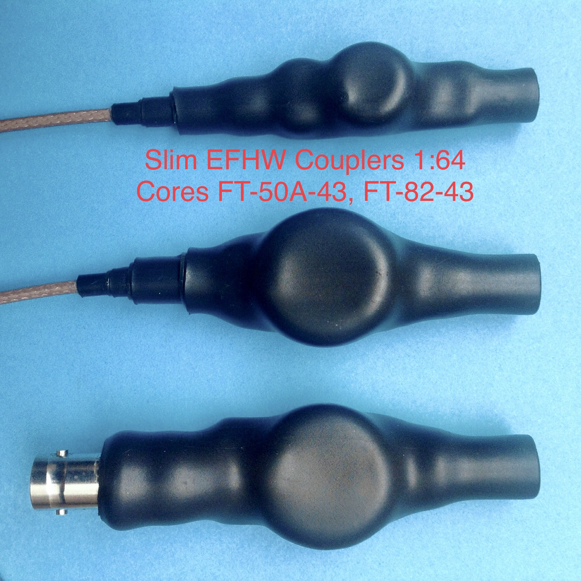
Ok Stephan, my project to improve the EFHW couplers used so far (in the slim design) lasted from spring 2018 to autumn 2019, that was a little longer than expected (…).

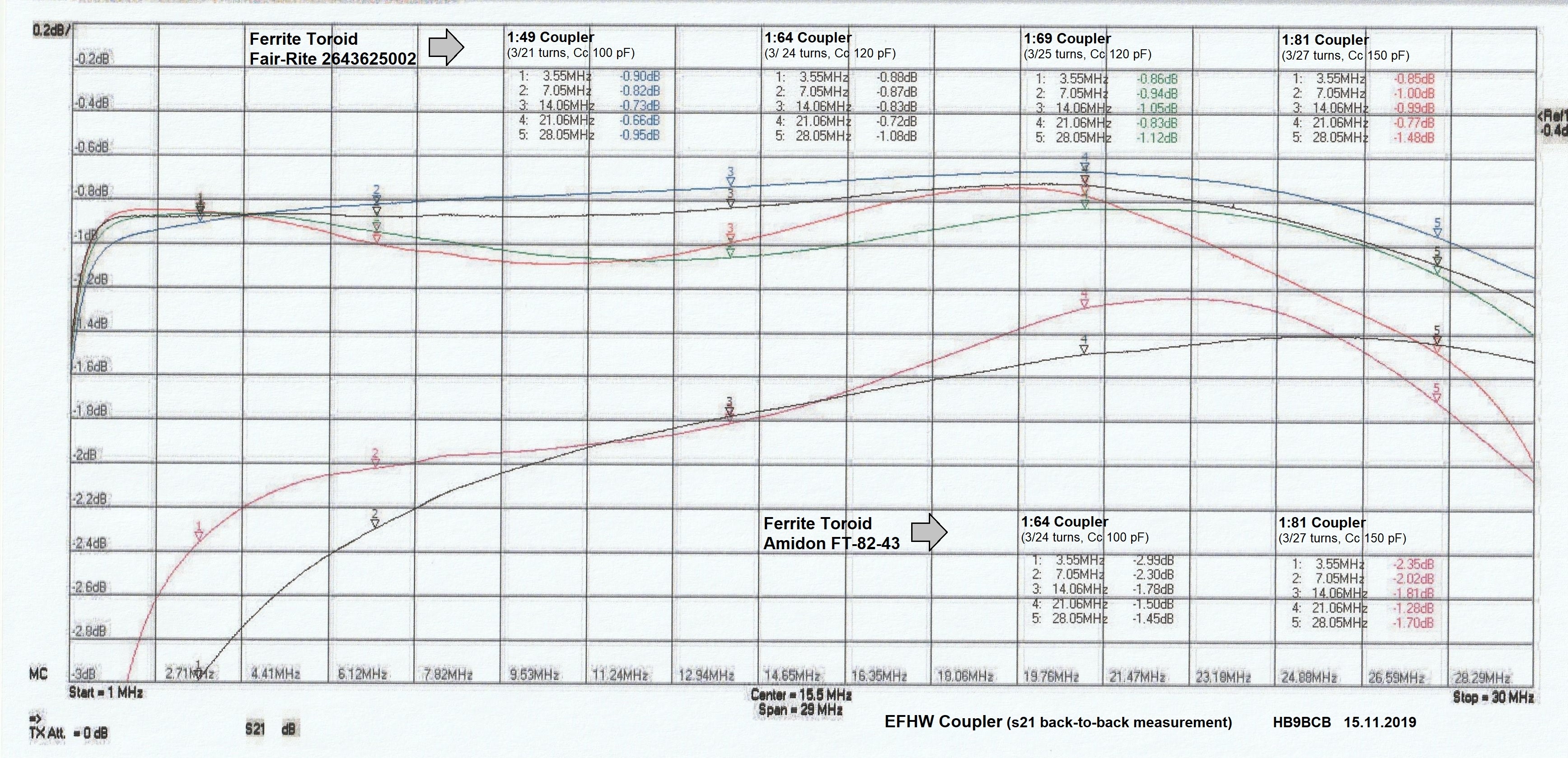
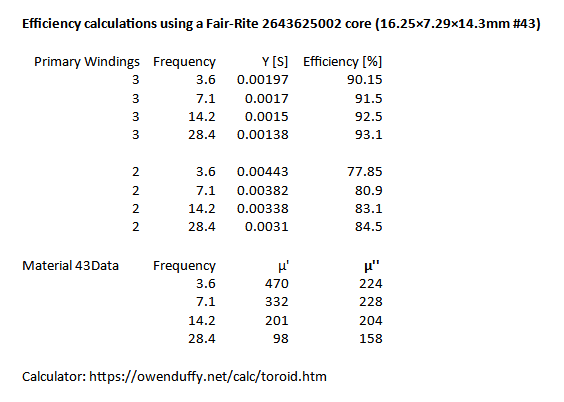
For this purpose, after a prior evaluation using the toroidal core calculator from Owen Duffy, prototype couplers 1:49, 1:64, 1:69, 1:81 were built, measured on the workbench on purely resistive loads and back-to-back and finally tested on real EFHW antennas for 80-10 m. The following ferrite cores were considered:

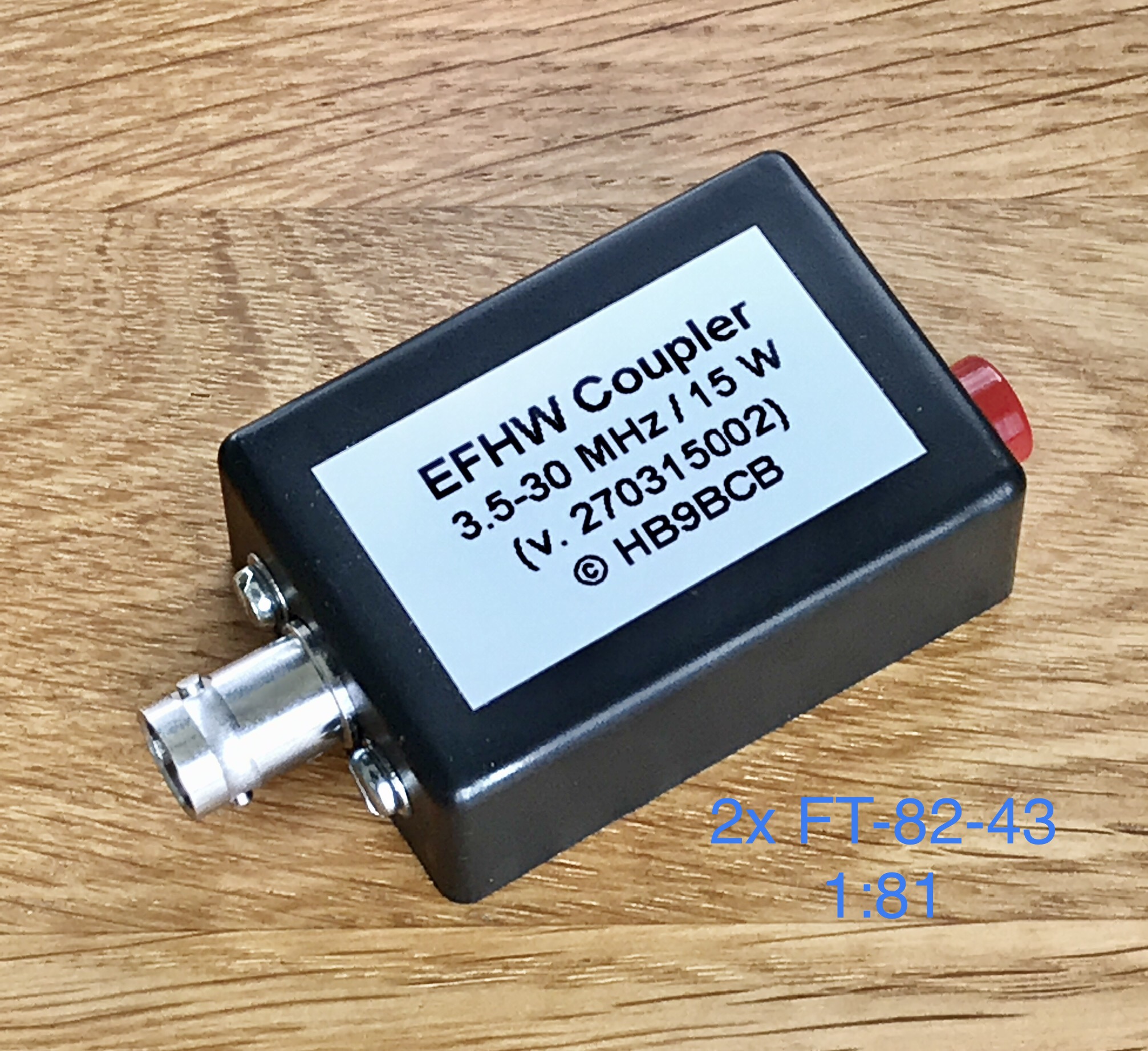
  • Amidon 2x FT-82-43, FT-140-43
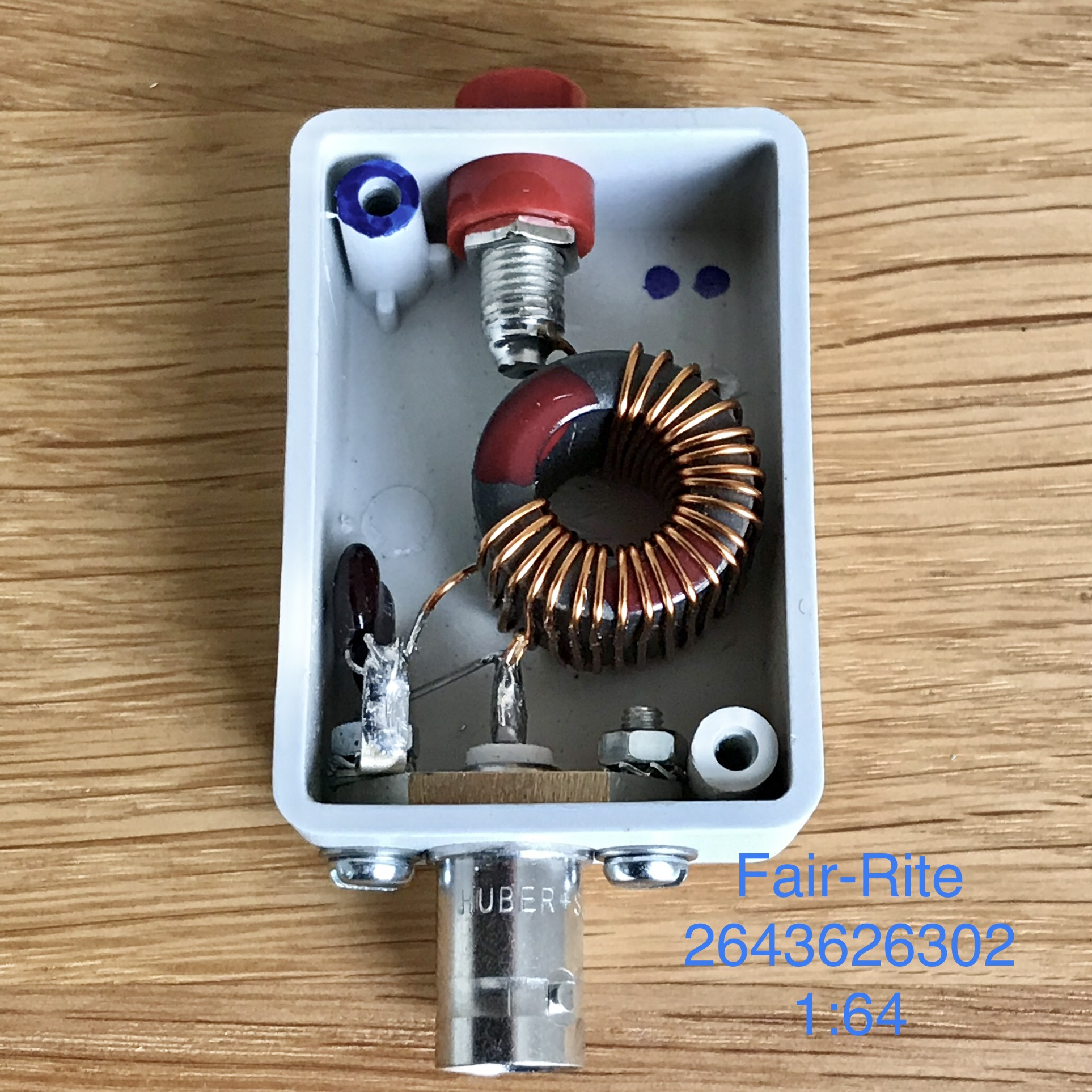
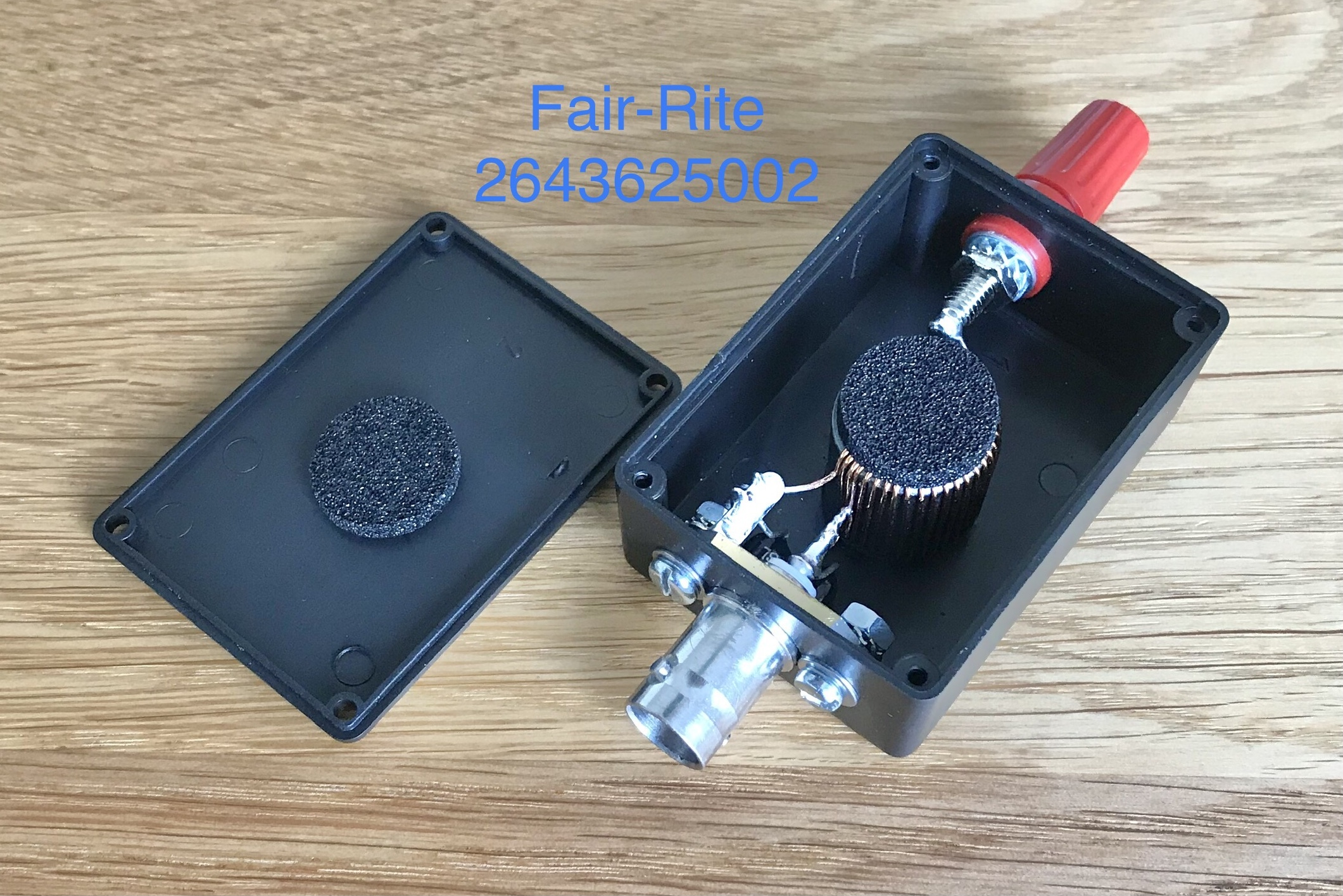
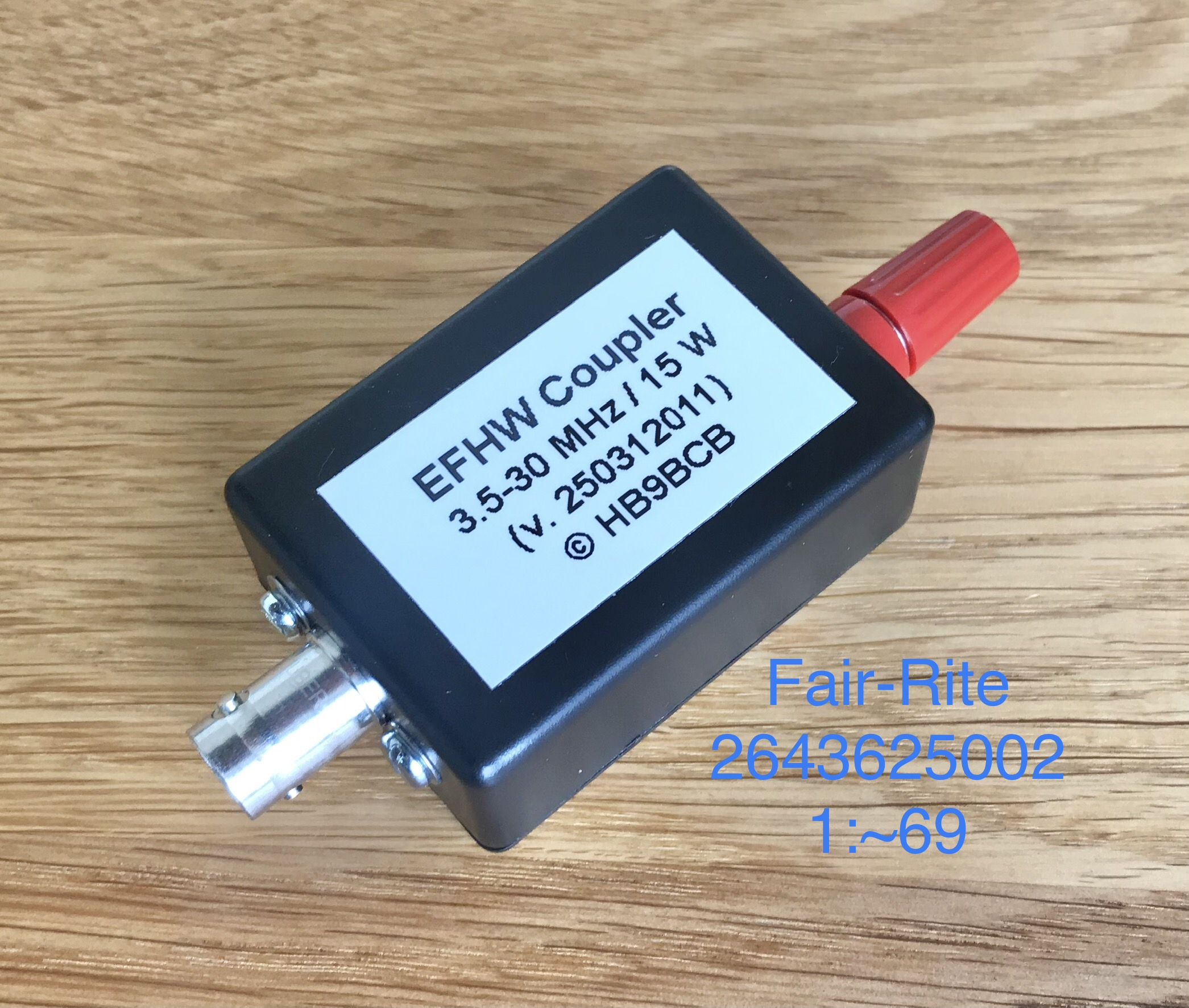
  • Fair-Rite 2643625002, 2643626302, 2643801202 (comparable to FT-114A-43)

During the measurements with the VNA SDR-Kits v3, the values ​​calculated by the toroid calculator have been confirmed quite well, taking into account the large tolerance of the AL value of the ferrite mix.

Core selection
Because at the time I was obsessed with the idea of ​​building the most efficient coupler possible, I chose the smallest Fair-Rite core 2643625002, which seems to be just sufficient for a load of max. 15 W cw/ssb and 10 W data.

Sticking points
Somewhat unexpectedly, some sticking points emerged during construction:

Point 1
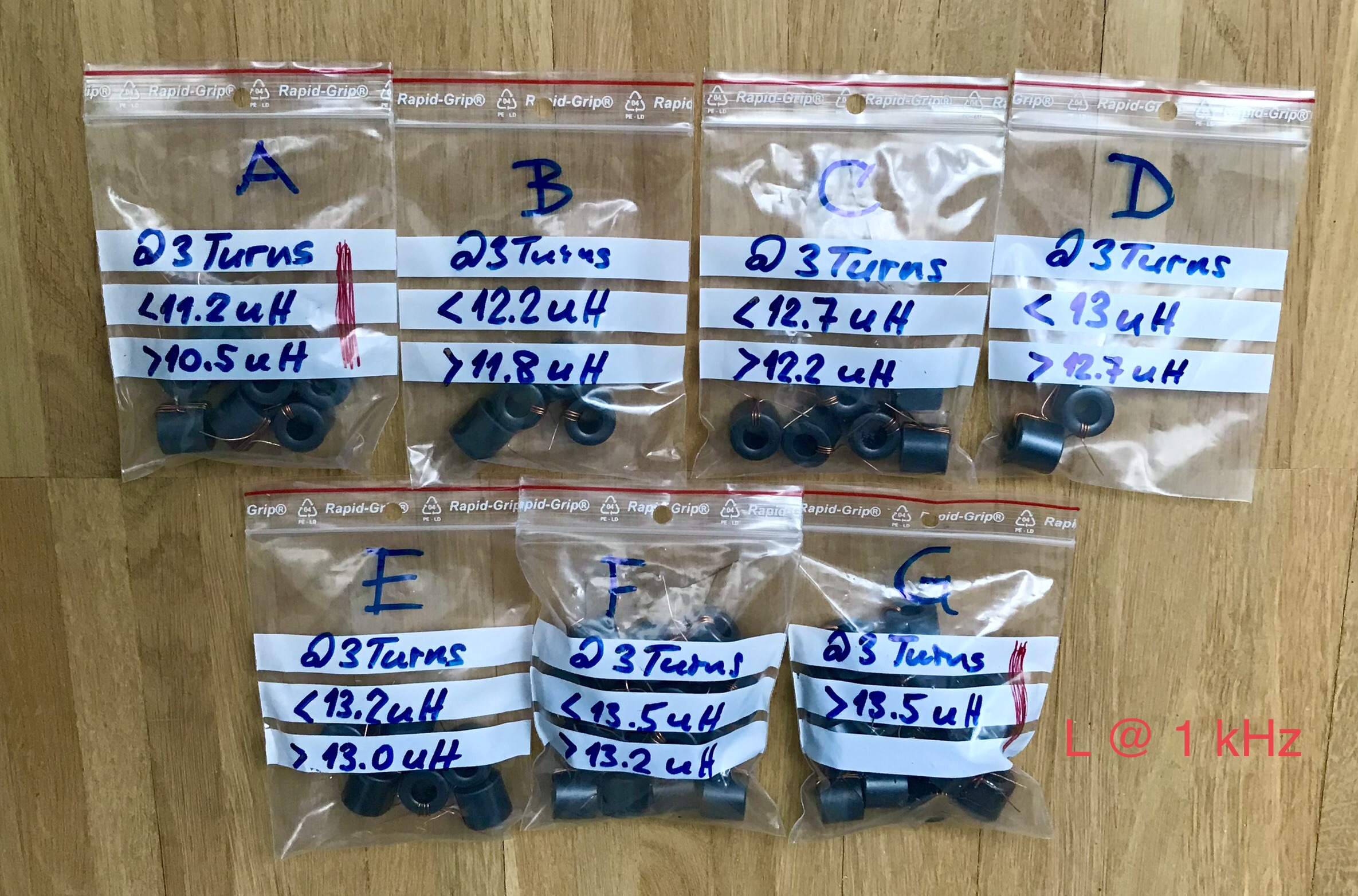
With the 20 toroidal cores from the 1st batch, it was not possible to build 1 pair of 1:49, 1:64 and 1:81 couplers each with almost identical electrical properties.
Reason: The AL value of the #43 ferrite mix varies by approx. 26% with this toroidal core (arithmetic mean of AL(1 kHz) = 1.344 uH/1 turn).

With 20 toroidal cores from a 2nd batch (from another supplier) this goal could just be achieved.
Another batch of 30 cores was then required in order to be able to build some couplers for my SOTA colleagues (…).

Point 2
The reasonably accurate reproducibility of a coupler was extremely difficult. This is not only due to the large tolerance of the mentioned AL value, but also to the fact that the coupler is very sensitive to stray capacitance. For example, unevenly spread “primary windings” had a strong effect on the electrical coupler properties.
Therefore, all turns were not only attached tightly, but then pushed together completely. That was almost a watchmaking job, hi.

Point 3
The aforementioned sensitivity to stray capacitance was also noticeable when it was installed in an (adequately small) housing. The stray capacitance due to the proximity to the housing material and, above all, to the material attached to fix the core also tugged a bit on the previously nice-looking graph curves.

Final tests and conclusion
The final tests with EFHW antennas for 80-10 m then only confirmed the well-known: Due to the complex and non-linear permeability of the ferrite material and the non-constant impedance of the EFHW antennas in the range of 80-10 m, which unfortunately do not neutralize each other, result mismatch losses.

These mismatch losses occur with the following tendency: Below approx. 10 MHz with a decreasing coupling ratio and above approx. 20 MHz with an increasing coupling ratio.

A 1:64 coupler is therefore best suited as a universal coupler for the entire frequency range, a 1:81 coupler for the range of approx. 80-15 m and a 1:49coupler for the range of approx. 30-10 m.

The 1:49 couplers are particularly popular with QRO enthusiasts because of their low transmission loss (-> heating), unimpressed by the high mismatch losses below approx. 10 MHz (…).

As the attached overview with the S21 graphs (of operational couplers) suggests, the project was successfully completed.

Would I choose the same toroidal core again? If at all I would probably use a slightly larger toroid.

73, Heinz

6 Likes