Seven SOTA antennas compared using WSPR on a summit

Five members of HB9SOTA have gathered on the summit of Gurten HB/BE-111 on July 2, 2017 to compare the following seven antennas using WSPR on 40/30/20/60m:

  • Linked EFHW inverted V
  • G5RV
  • Trapped EFHW inverted V
  • EARC End-Fed (9:1 UNUN)
  • G8JNJ (modified for SOTA)
  • Vertical with one radial
  • Fuchs antenna

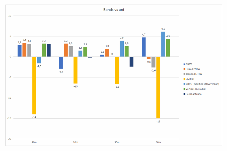
To get straight to the point: six of the seven tested antennas were very similar in performance; most differences were in the range of 0.5 S levels, so not really relevant for SOTA purposes. It seems that given a reasonable length of wire compared to the wavelength, and barring obvious mistakes that lead to significant losses, the exact type of antenna/coupler does not make such a big difference in practice.

A PDF with a description and photos of each antenna, as well as summarized performance statistics, is available here: https://hb9sota.ch/wp-content/uploads/2017/07/wspr_gurten_hb9sota_20170702_en.pdf.

Below are some links with a detailed report generated from the WSPR spots per band:

40m: WSPRviz
20m: WSPRviz
30m: WSPRviz
60m: WSPRviz

The reports were generated using software that I have written for the purpose. The central part is a kind of “SNR difference matrix”. For this matrix, only spots were considered where the same spotter received signals from two or more antennas at the same time, and those spots were then used to calculate the SNR differences (TX power normalized) among the involved antennas. In this way, it is possible to reduce the influence of changing propagation and receiver QRM and allow for a more or less fair comparison. However, it has to be said that by principle, this method does not take different antenna characteristics into account. For example, if an antenna has a very low radiation angle and therefore generates some DX spots, but on the other hand produces weaker signals in the near range, it could on average show lower performance than an antenna with a high radiation angle that produces a lot of strong spots in the near range. To better evaluate this, spots are also shown graphically on a map, and in a statistic with average SNRs per distance range.

Some antennas have generated DX spots (VK) on 20m and 30m, but they were pretty close to the decoding threshold (as was to be expected given the time of day and band conditions), and there were only one or two spots per antenna, so not enough to say much about the relative “DX performance”. No North American spots at all; we’re hoping for better band conditions next time.

On 60m, most antennas were used in a “makeshift” configuration using ATUs, which reflects the current common practice in HB9 (as an inefficient 60m antenna often still works better than a resonant 40m antenna for intra-HB9 contacts).

While we have attempted to be as rigorous as possible, there are obviously some challenges associated with getting five OMs with seven antennas to transmit at the same time on a summit in slightly rainy weather.

Five antennas were each fed with a KX3 @ 5 W. One antenna was fed with a KX2 and one with an FT817. Smartphone WSPR apps were used as the signal sources. The output power of all rigs was measured using a WM-2 QRP wattmeter + dummy load, and the results were adjusted accordingly. Non-overlapping WSPR AFs were assigned to each antenna/rig combination, so that at least there would be no overlap between the participating members (of course one cannot anticipate WSPR transmissions by other OMs elsewhere). To ensure that transmissions are within the WSPR band, the LO of each rig was checked using a rubidium standard, and adjusted if necessary.

HB9SOTA intends to repeat this comparison in the future, perhaps with a focus on minimal antennas like loops or whips, so that operators can weigh the benefits of lighter size and ease of use against the weaker signals to be expected.

73,

Manuel HB9DQM

34 Likes

Thank you!

This will be useful for everybody. :slight_smile:

Congrats for a job well done.

Vy 73 de Pedro, CT1DBS/CU3HF

1 Like

Thanks Manuel - interesting analysis. It is indeed a shame that conditions were so poor for your test as it won’t be easy to do it again.

2 Likes

Thank You for your work! Great info and my biggest take away from the data is to walk away from my EARC style antenna…9:1 balun & 42’ wire. I never expected stellar performance but WOW this data sure in an eye opener.

2 Likes

Wait! :wink: Before you abandon your EARC antenna, consider the possibility that something was wrong with the particular antenna/setup used in this test, making performance worse than for EARC style antennas in general. I’ve never used one myself, but running an ATU through a significant length of coax (the EARC guide recommends “16’ or longer, with the coax shield providing the counterpoise function”) can be a recipe for weak signals — especially if it’s 10 meters of RG174 as in this test…

1 Like

It might be that the matchbox used in the EARCHI antenna is lossy. That is about the only way to get 6 to 15 dB down with a full-sized wire antenna. They use a powdered iron core, but I don’t know whether that is lossy.

The 9:1 transformer from Balun Designs uses a ferrite core.

There is further discussion of matchbox design here:

http://www.eham.net/ehamforum/smf/index.php/topic,105998.0.html

wunder

1 Like

Hi Manuel

Taking data from your reports, one is able to produce the following graphics.

73 de Pedro, CT1DBS/CU3HF

4 Likes

All you say is true. I am not throwing it away yet - may still come in handy. I wound the unun using a ferrite core robbed from a no longer used balun made by LDG. Had decent results in terms of SWR and no RF in the shack with 20’ of RG-58. For now though, I have a 66 ft doublet made of #22 wire and 300 ohm twinlead that works well when I operate portable. So, I won’t give up on it - just won’t be #1 in my choices.

1 Like

Did I read it right, the EARC was only 9 metres long? Kinda short if you ask me. I have one that I have never used yet for SOTA that’s 56’ (17.1 metres). Works good for when I have had it up.

Malen
VE6VID

This is a really, really useful contribution! Thanks for your excellent work!

Martin, DK3IT

3 Likes

Yes, I would have to agree. A really, really useful contribution.

1 Like

Wow, thanks for your work guys,it’s appreciated! Will take some time to read all the data.
Though I find 3 dB rather relevant.

differences were in the range of 0.5 S levels, so not really relevant for SOTA purposes.

Ahoi
Pom

2 Likes

Yes, that’s correct. As I said – it may well be that the problem was just with this particular antenna, and not EARC antennas in general (although I still find the concept of tuning through a significant length of coax problematic). Maybe we’ll have another example of a similar antenna the next time we do a WSPR comparison :smile:

The main problem seems obviously not to be the length of the counterpoise (coax shield) but the length (impedance) of the radiator used on a certain frequency band.
Because an 1: 9 impedance transformer is used, the design impedance of the radiator should be in the range of 450 ohm - on each of the frequency bands to be used.

In view of this fact, it is not quite plausible that the EARC Manual proposes one single radiator length of 24-60 ft for best efficiency of a 6-40 m Multiband end-fed Antenna (not to be confused with EFHW).
Just as an example, the 30 ft antenna wire delivered with the EARC kit is about a quarter-wave radiator on 40m (impedance around 45 ohm) and about a half-wave radiator on 20m (impedance around 3000 ohm). The mismatch with the 450 ohm impedance transformer is obvious.

That something must be suspicious with this recommendation one can see e.g. when looking at the voltage/impedance characteristics for antenna wire lengths up to 20 m (65 ft) provided by http://dl7ahw.bplaced.net/Antennenlaenge.html

So my suggestion would be to build a modified EARC antenna with links - to keep the design impedance on all frequency bands as well as possible.

2 Likes

Thanks for your work…

1 Like

This is a great report. Thanks.

I also tend to conclude that the issue for the antenna with the 9:1 starts with the antenna length. In theory, wire lengths similar to the longer leg of a windom antenna gives similar impedances on harmonic bands, for example. But it can be seen in Heinz’ diagramm above how sensitive that is.

A similar loss mechanism might be there for this G5RV on 20m (not to argue if -3dB is noticable or not): 2x11.6m create a rather high impendance. The 75ohm twinline is about half wavelength --> high VSWR and high impedance again. Then 50ohms 5m RG58. About quarter wavelenght --> rather low impedance at the ATU which might add some further losses.

Great report …

Lars
DL8WJM

1 Like

Strange findings on the EARC endfed …
Just home from my 9 day SOTA tour, and used this antenna for most of my activations.
I carried a fullsize link-dipole (40-6m) too, but the endfed is so much easier to put up, and gives instant band change (handy when looking for S2S !).
I compensate the lower efficiency of the EARC by using 15W from the KX3.

The pdf doesn’t mention if a “counterpoise” was used ?
My wire is 9.15m, but I always use 4m of wire connected to the ground lug, and don’t put it on the ground if possible, but tie it to a tree or bush (so making a “mini windom” in fact).
One activation was with a 20.3m EFHW and 49:1 transformer, SWR 1.5 on 40M without tuner, but results seemed not “spectacular” compared to my EARC endfed.
(of course this was just one instant, maybe bad propagation that day)

NOTE : I don’t wind the radiator around the pole, but use a 6m pole and put the wire as a sloper.
Maybe more food for study : effect of a glassfibre pole on radiation/impedance etc … ?
Also : in a future test, I would like to see an “ordinary” dipole in the comparisons.

Now that I won the WsprLite … I hope to start some tests soon myself :wink:
73,
Luc ON7DQ
PS : and thanks for all the contacts ! Now have to do some more unpacking …

2 Likes

Referring to the diagrams plotted by DL7AHW was done with the intention to visualize the wave propagation on an antenna, especially for HAMs of the “ATU generation” (sorry for this expression).
But be careful: The wire lengths shown in the diagrams are valid for free space conditions AND with a proper termination (in the best/simplest form as a dipole).
So these lengths have to be adapted in practice, but the characteristic remains the same.

1 Like

c[quote=“ON7DQ, post:17, topic:15635, full:true”]
My wire is 9.15m, but I always use 4m of wire connected to the ground lug, and don’t put it on the ground if possible, but tie it to a tree or bush (so making a “mini windom” in fact).
[/quote]

The easiest way to significantly improve the efficiency of your “EARC” antenna: Add a 2nd radial of the same length (in opposite direction) and omit the 1:9 impedance transformer (no typoo …). Well, you will have to use the KX3/ATU then …
Have fun!

Edit: Coax feedline (if used) should be kept within 2-3m (as long as necessary at some locations…) with this modified antenna. Of course, this antenna can be arranged as vertical, inv-V or inv-L depending on the local space conditions.

3 Likes

Hi Heinz

Could you imagine that we call it a dipole?!..
And if you do some math and make each wire 1/4 wave long of the frequency in use it would work without an ATU… :wink:

73 de Pedro, CT1DBS/CU3HF