Phil AD5X published one in QST this year. It used a relay to bypass a pair of power diodes. The default state was power diodes in circuit but when the voltage dropped the voltage switch powered the relay and shorted the diodes. The result was it failed safe by putting the dropping diodes in circuit. Nice and cute idea.
Then you waste ~200mA powering the coil continuously, latching relay would be the best, unless you favored dropping the voltage down first with a DPST relay Still working on my converter.
Jonathan.
Next best thing to a latching relay would be to use a ‘normally closed’ contact pair to short out a resistor in series with the coil. The ‘hold’ current is a lot less than the ‘operate’ current, depending on the spring loading etc. Select resistor value for the particular relay.
In this application there should never be more than a volt or so across the main contacts, so you could slacken off the spring load quite a lot too, as it is mainly to open the contacts quickly to minimise arcing. That would minimise the hold current…
Adrian
G4AZS
Many ways to do it, A D-type FF could also be used with a buffer.
Problem I have often found with relays is that they change with temperature. I have found this with soft-start circuits using series coil resistors, though I suppose in this application the point of switching is not important.
Its an interesting idea. It has got me thinking, I still have two 1N5401’s in series on my pack.
Jonathan
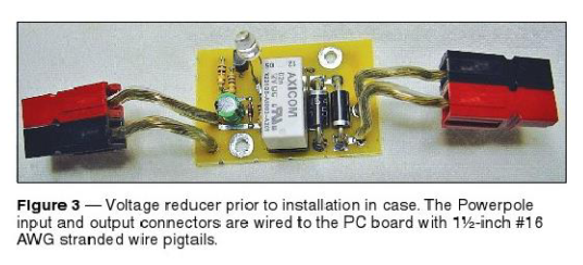
Here are AD5X’s non-automatic voltage reducers. They are in-line with power poles. One even has an LED!
http://www.ad5x.com/images/Articles/Vreducer.pdf
http://www.ad5x.com/images/Articles/LiPo%20Battery%20Reducer.pdf
wunder
Looks like Phil’s webserver has been slashdotted by the SOTA crowd 
After Phil’s webserver gave up in disgust, I looked through my QSTs (I get the online only subscription and print the whole issue to PDF for use on the tablet).
One he does the circuit the other way around, the relay is powered when the volts are high and that puts the diodes in circuit. So if the voltage detector/relay failed it could put all 16.8V on the output. And secondly, he isn’t using the relay out of Ferrybridge Power Station that switches all 2GW output but something smaller. So the operating current is 26mA not 200mA!
Now I admit to getting grumpier, senile and confused as I age so it must have been me that thought, “oh no swap the logic so it fails safe” and not Phil and I’ve thought it such a spiffingly top notch idea I’ve subconsciously donated it back to Phil.
Anyway, QST April 2015 page 39.
I was thinking along the lines of an automotive relay coil R = 80-90 Ohms. You would get those currents with a PCB relay though - be a real nuisance to solder, but yes it would work better.
Indeed, a PCB relay is what is used. here’s the completed unit ( © ARRL).
I’m not posting the circuit, buy the magazine if you want to see what it is!
Very neat ! Homebrew PCB as well gets my vote…
Ah, I knew I had seen it somewhere recently ![]()
Victor GI4ONL
Hi Peter,
I’ve been trawling all the yagi design sites for some time now, and have decided I think my best bet is one of the DK7ZB designs like you have used.
I’m taking it you built Type 1 from that page, with the nicest SWR plot?
Did you apply a boom correction on the elements, and if so, what sums did you use?
How are you retaining the directors and reflector? (I can’t really tell from your page)
Looks like you have drilled the driven element sections? I remember flattening and drilling a 4mm hole in 4mm elements for my DJ9BV contest yagis. That was ‘fun’ ![]()
Did you model for the offset driven?
I use my Kenwood ts480 for sota as its my only HF rig and its 4kg. I have swapped a 12 ah slab battery for a 4200mah lifepo4 battery from hobbyking. Its only 500g in weight compared to 2 or 3kg of the slab.