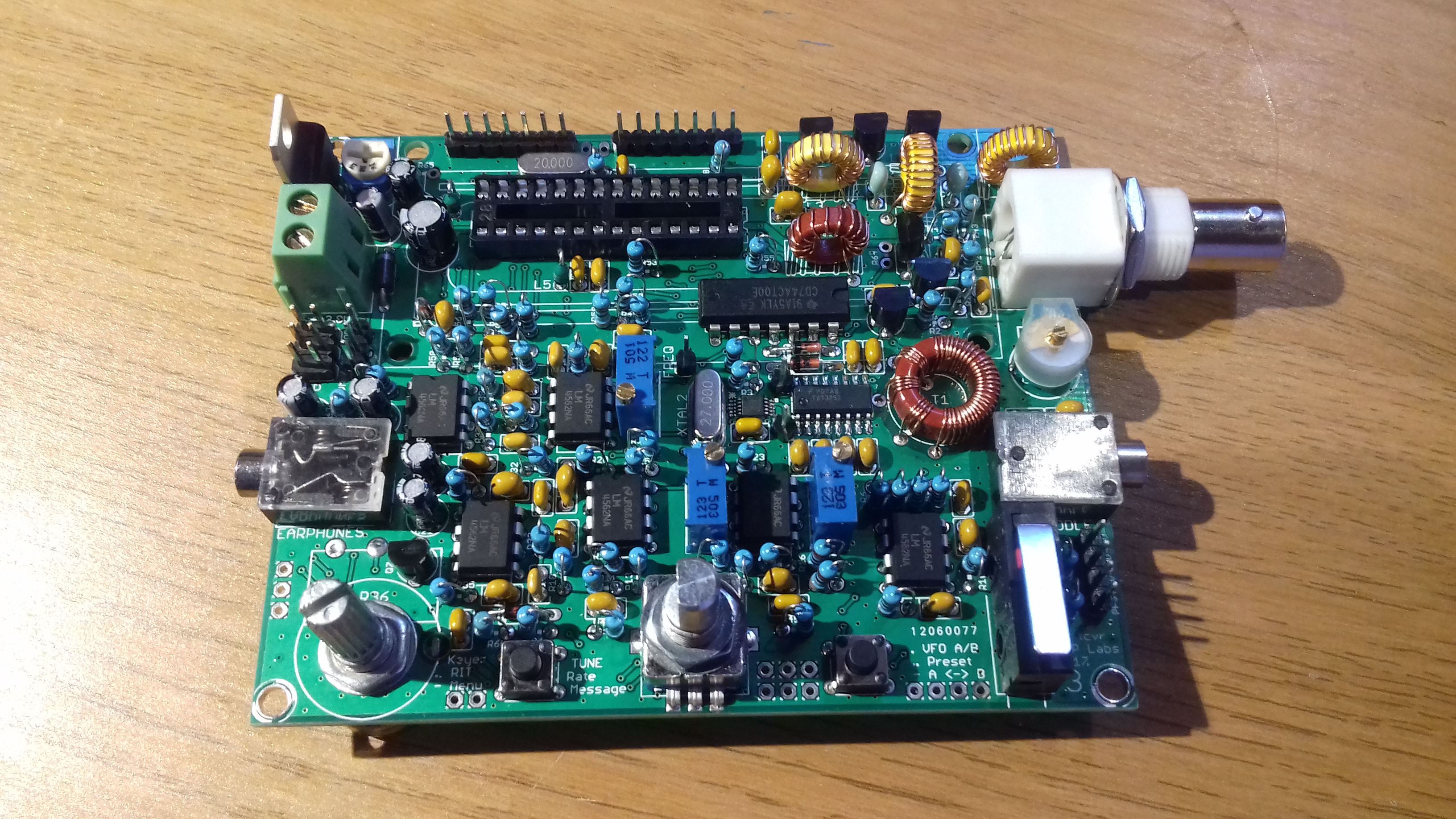
Started building my QCX yesterday but didn’t spend a lot of time on it. I’ve almost run out of solder (I seem to get through quite a bit!), hopefully the post lady will bring me some more at the weekend.
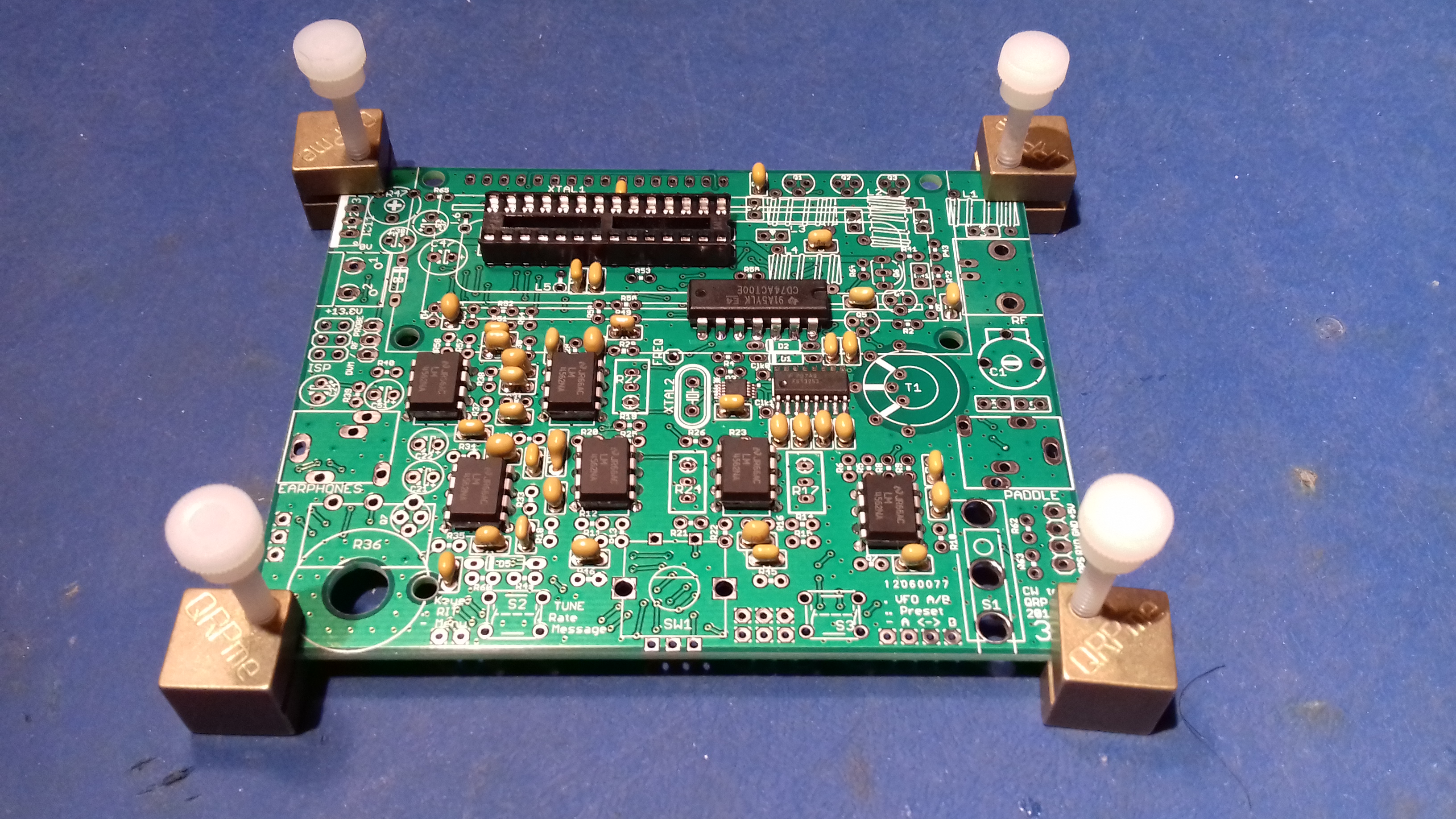
It’s deceptive just how many caps and resistors have to be fitted to the board!
This was the board yesterday evening, today I installed all the resistors but didn’t take a pic.
Build instructions are the best I have ever encountered. It is easy to build for someone with a little experience. Radio has a great rcvr, incredible radio for the price. All that noted, the radio was not specifically designed for SOTA use, and presents some awkwardness to set up, compared to say, the MTR3 and MTR5 (but those radios are MUCH more costly and are not presently kits). 73 - fred KT5X (aka WS0TA)
Mine is in a nice case. . . still wrapped up in its original packaging case, not built yet lol. How long before its the oldest kit never built in original packaging?
I have completed the build of my 30m QCX, and it all works - except that the RF power output is only 0.5W.
Pulling L1 and L3, and measuring them on my Peak LCR40 shows them to be 0.7 and 0.6 microhenries respectively, when they should be 1.1. I have checked the number of turns!
I’m not sure whether that would account for the low output, but I think I’ll rewind them on known good cores anyway…
The components seem very cheap in this kit, the resistor leads are very thin for example. I don’t feel badly done to though, it’s still a lot of radio for the money.
I haven’t done any building today, I went with the family for a walk on the moors above Haworth, the famous Bronte country in the sunshine. The highest point we got to was Top Withins Top Withens - Wikipedia Sadly not a SOTA summit anywhere near
I have asked Hans G0UPL and please read his answer below
There is nothing wrong with the toroids in the QCX kit. Some people measured them for a comparison and found them to have a higher Q than the common micrometals toroids. But still within comparable specifications which are quite wide. The inductance variation is also wide, for both micrometals toroids and these. Measuring the inductance is ideal. People also often do not realize that the winding style greatly influences the inductance. Squeezing or spacing out the turns can change the inductance by a factor of 2 or more! There is no need to replace the cores in the kit, the same issues of variation in inductance will still apply.
There is nothing wrong with the resistors either! They are a low wattage type, they are perfectly well suited for the application. Good engineering is about maximising performance and features, while minimizing costs. In other words, optimizing “Value”!
Thank you for posting Hans’ comments on this, they are reassuring!
The instructions do explain that the toroids will vary a little, and that the absolute inductance values are not critical in the low pass filter.
I think the kit is excellent value, the design and the instructions have clearly been given a lot of thought. I especially like the detailed explanation of how each part of the circuit works.
I haven’t yet found why my QCX has low output, though it is likely to be human error on my part…
Investigating the toroids is just part of my working out what is wrong, and all part of the fun / learning.
I used the supplied cores.
I did remove 1 turn from each core L1 - L4, and my turns are evenly spaced on the cores.
Now I get 5W if I feed the QCX (20m band) with 16.8V (I left the “stupid-Luc-diode” in circuit)
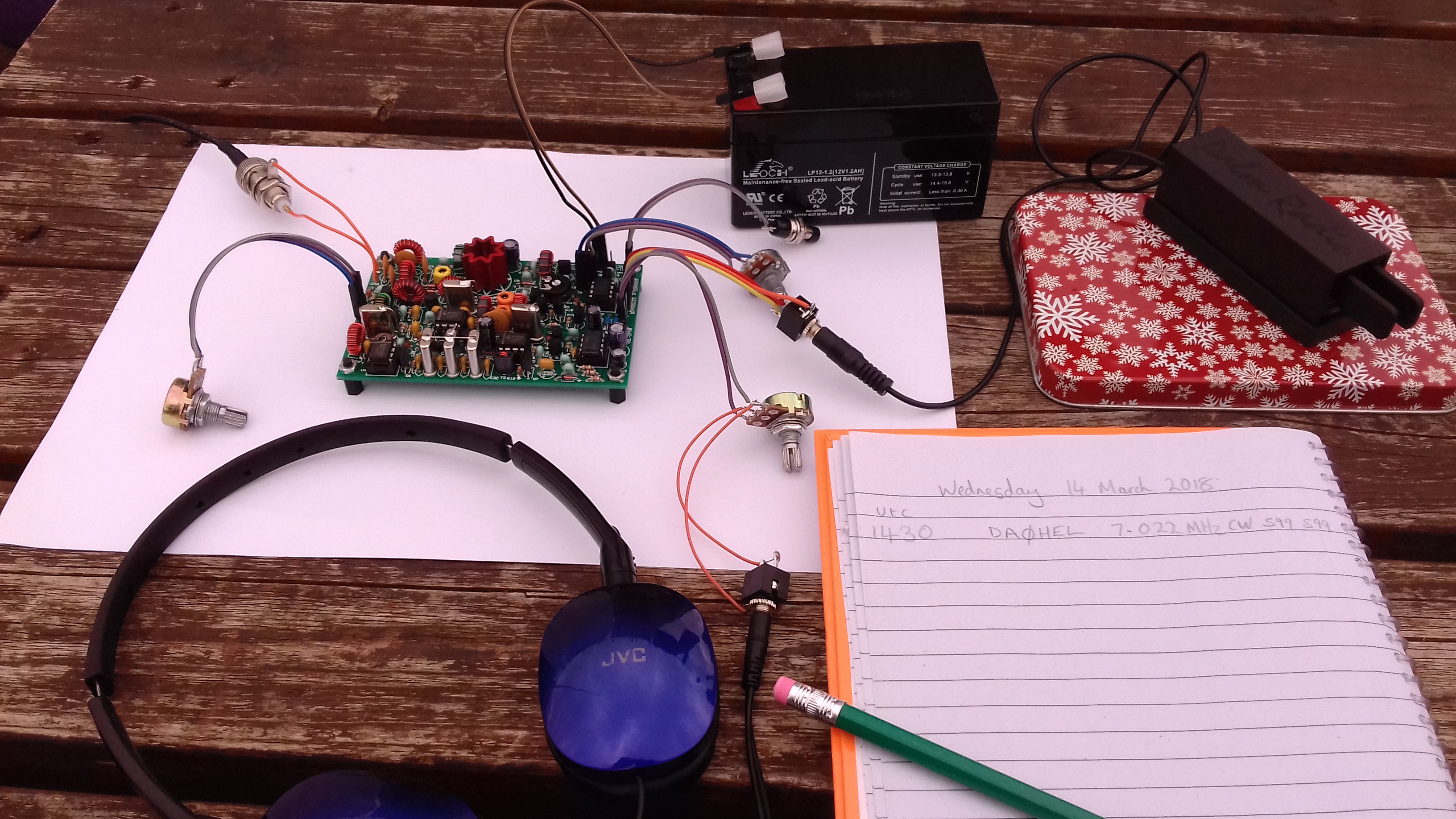
I did glue a small heatsink to the three BS170’s, pictures are in the groups.io , in an album named “ON7DQ” if you want to see how I did that.
(not sure if a direct link works, I suppose you will have to login: Log In)
Thanks for your comments - before you removed one turn, what was the output?
I’ll be happy with 2 or 3 watts out, but 0.5 seems very low, so something is not right with mine at the moment…
Using the built in power meter, and connecting it directly to the Drain of the output mosfets gives a reading of 5.1 Watts. The instructions point out that this is only an indication, because the waveform at the Drain of a class E stage will be far from sinusoidal - but it does seem that the problem is in the low pass filter…
I have been looking in the qrplabs groups.io, but it seems that I need to register and login to see your album - I will do that, thanks.
Just check the soldering on the wires on those toroids in case you didn’t get it hot enough to strip the enamel insulation from the wire. You may have an unintentional series capacitor!
I’m open to all suggestions, Andy, and soldering the enamel wire is a common problem worth mentioning.
I have checked, though, and there is DC continuity between the filter input and the BNC output connector.
I’ve also checked that the LCD mounting lug is not in contact with the winding, which can be an issue.
I’ll pick through it again this afternoon, and see what I’ve overlooked / messed up!
That’s a bit extreme in my experience, 20% is about the most variation I’ve ever seen (on toroidal cores - small air-cored solenoid coils can easily be adjusted by 100% or more!) but I do always check the inductance when I’ve finished winding. (I can recommend the Peak LCR45 - much more manageable than my old Marconi LCR bridge…) It’s very useful having a bit of wiggle-room to interpolate between integer numbers of turns. Still haven’t mastered half turns on toroids
When I’ve got the inductance just right a few drops of beeswax melted onto the turns with a warm soldering iron holds them in place whilst not completely ruling out future adjustment!
Well, my earlier measurements were made at 12v supply - typical of what I would use when activating.
The RF output is greater with a higher voltage, but still rather low.
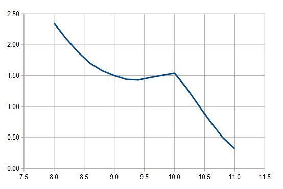
The 30m QCX will tune a few Mhz each side of the band, so I decided to do a frequency run, and plot the RF output at 200KHz intervals, from 8 to 11 MHz.
I did this with a 13.8V supply, using the built in power meter connected to the output, and with a good 50 ohm dummy load. The result is shown below.
Interestingly, it suggests that the low pass filter is cutting off a bit sharply at 10MHz, but also that taking a turn or two off each toroid and shifting the response higher might well increase the output at 10MHz.
I guess there is more to this than simply the filter frequency response, as I think class E amplifiers are quite fussy about the reactance of the load presented to them, but without a lot more reading up, I’m not qualified to comment!
Anyway, I think there is probably no hard fault with my unit, just a bit of tweaking to do…
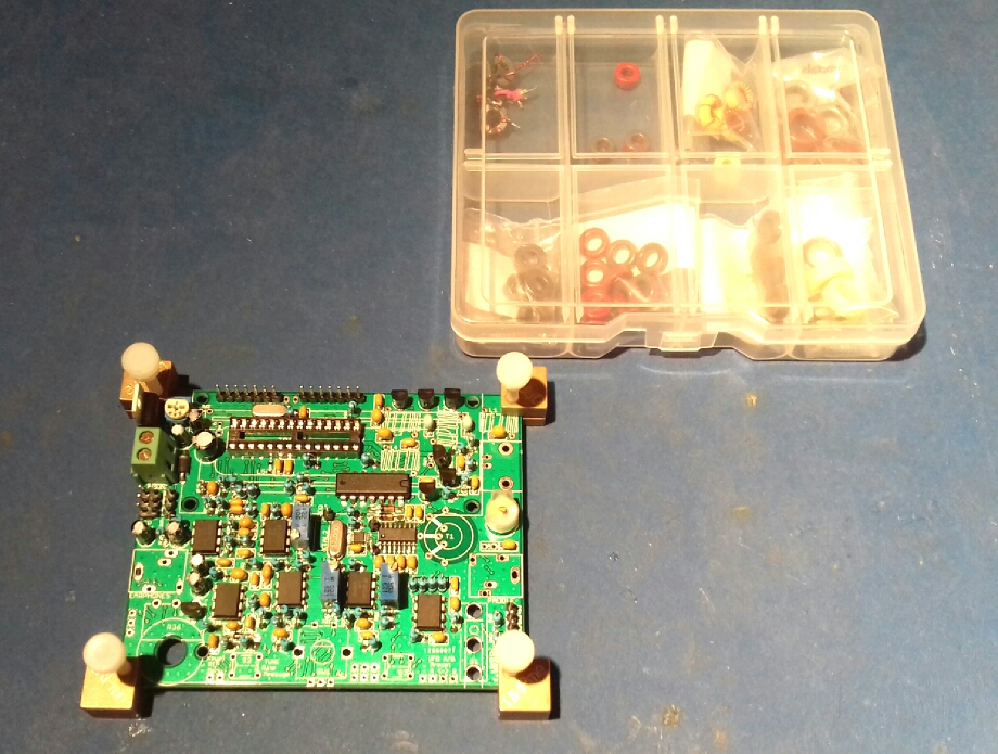
I hope to power up my board tonight. I’ve added all the toroids now, I checked them all with my LC meter and they were all exactly at the expected value. I just have the display to add then I can try powering up the QCX for the first time.
Like Paul states, I’ve never noticed massive deviations in values with toroids that I’ve wound, compressing or spacing the turns gives a bit of wiggle room but nothing huge.
With the MTRs that I’ve built, which use a very similar style class E PA, adjusting the spacing of the turns on the toroids does affect the power output, so it’s worth having a play to find a sweet spot.