Bought the kit from qrpguys today. 
Something you might consider - a width/section of computer ribbon cable 3, 4, 5…conductor, each one cut for a different band. Would be like carrying one radial/cpoise instead of a bunch of wires. Or - an appropriate length of telephone cable cut for 40m. Pick one conductor (usually there are 4) to keep long for 40m, then measure and mark points for 3 other bands. Make a 1-2" slit by each mark, open the slit, pull out (slightly) the desired wire to be trimmed and cut a 1" or so piece out. Again, carrying one wire which in reality is 4 band counterpoises.
IMHO, that will never work. The wires are too closely spaced to achieve individual resonance. They need to be spaced several inches minimum.
73, Barry N1EU
Let’s say I wanted to adopt this kit on a 33’ vertical radiator on 40, 60, and 80m.
Using:
http://www.homepages.ed.ac.uk/jwp/radio/software/loading.html
With 3.55 as the design frequency for 80m, using 24 gauge wire with the inductance at 0 ft (base loading) the program spit out 25.7 micro Henry.
Then using: Toroid Winding Calculator • 66pacific.com
For 5.357 for 60m I was given a value of 6.47 microhenry
Using the stock torroid, a T-68-2 that comes with the kit would be 34 turns for 6.6 uh.
I replaced the 40m torroid with a T-68-3 for 18.7 micro henry spit out with 31 turns.
Then put the 80m torroid in the 40m spot on the board, and the 60m in the 30m spot and that should work in essence right? Or am I missing something?
I think I made a mistake as type 3 material is high q from 0.05-0.5 MHz. Blue type 1 would be better, but I would need to fit 41 turns on there.
I guess you could stack 2 T68-1 cores and run 20 turns through it instead.
Hi Evan,
The way the board works is that for the lowest frequency band the two toroids are used in series. The middle frequency uses just one of the toroids (whichever you chose) and for the highest band both toroids are shorted out.
So your 33’ vertical is the 40m quarter wave with both switches set to short out the toroids.
Then you have one toroid wound with the needed inductance to load the 40m quarter wave to work on 60m and the third toroid is wound to add the needed extra inductence required to make the required total inductance loading needed to make the 40m quarter wave work on 80m.
In my 20/40/60m version, I need 11.5 uH to make the 20m quarter wave work on 40m and a total of 23 uH to make it work on 60m. So purely as a coincidence, my two toroids need to be the same value. which calculates out as 44.9 turns on the T68-2 cores. So I wound them as 45 turns. My tests yesterday show them as too low in frequency, so I have now removed one turn (i.e. now 44T) from each and will try again. For a finer reduction (and hence increase in frequency) I can remove one turn from just one toroid. This further action would also apply if e.g. 40m is close but 60m still low - in which case the second in series toroid (the one before the driven element) would need a slight reduction in inductance. For the absolute finest adjustment, the wires can be spaced out or pushed together on the toroid (and then glued).
73 Ed.
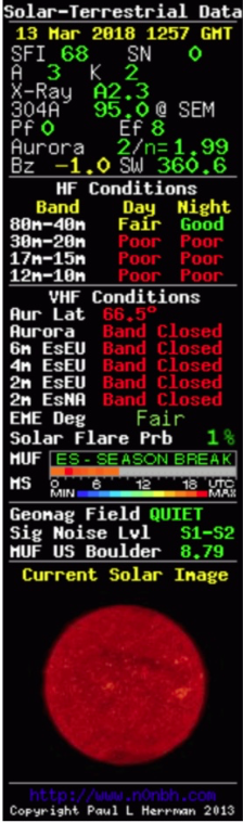
Today, I was able to test the new design on the air. I used a single, elevated radial with a loading coil for the radial of ca. 6 uH directly at the feed-point. Despite the shortened radial, the antenna worked pretty well on 40m and okay on 30m, despite the poor CONDX on 30m.
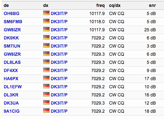
On 40m, I got four RBN spots netween 10 and 18 dB and two of 5 and 9 dB, so well workable, from 5 W tx power.
On 30m, I got one surprising of 25 dB by GW8IZR and 5 dB by OH6BG and SM6FMB, but I think the performance on 30m is hard to judge given the CONDX.
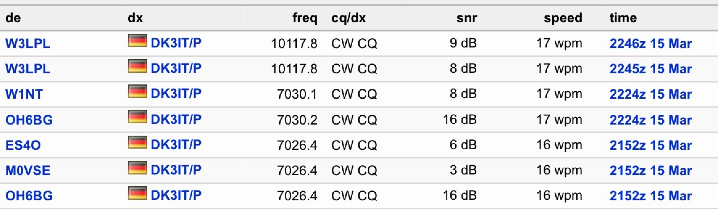
Attached, please find screenshots of RBN and the HF condx.
What I will still have to evaluate is if I will tie together three tuned radials, one for each band, or use a single tunable with the loading coil for 40 and 30 m and another optional one for 20m.
But I was really surprised how well this very short up-and-outer worked on 40m, given that the radiator was only 5.17m and the radial even a bit shorter, and that the loading coils are using toroids instead of being air coils.
The radial was ca. 40 cm above ground.
An open question is how well this will work in various terrain.
73 de Martin, DK3IT
One thing I’ve noticed using the stock qrpguys setup is that swr varies widely depending on terrain. In sand (which I imagine must be like non ferrous stone) I couldn’t get swr under 3:1. On “normal” soil, it was fine. One data point of course.
Maybe this could be true - if the noise level at the spotter was not astronomically deep (sometimes the S/N ratio is misunderstood to be the absolute signal level)?
Hello Martin, how about the single shortened radial?
I’m following this very interesting thread since its beginning…
Thanks de Fabio
I had the variable SWR issue on a similar antenna some years ago. While it worked admirably at home mounted over grass covered clay ground, on a rocky summit in Portugal the SWR reached 3:1 which caused a problem for the FT-817 and I got an RF burn off my key. Considerable fiddling and adjustment was required to get it to work. The next time I used the antenna in Portugal I took an inline RF choke with me and it worked much better. Now I prefer links for band switching, though does require 5 links each time as I use 4 radials / counterpoises.
Hi Heinz:
I did a quick analysis over raw RBN data. Here is the mean SNR in dB for the skimmers that spotted me (40m, , only DL stations, only CW):
Skimmer:     9A1CIG SNR Median 23.0 dB
Skimmer:      DK3UA SNR Median 17.5 dB
Skimmer:      DL3KR SNR Median 21.0 dB
Skimmer:     DL1EFW SNR Median 15.0 dB
Skimmer:      HA6PX SNR Median 20.0 dB
Skimmer:      DF4XX SNR Median 12.5 dB
Skimmer:     DL8LAS SNR Median 11.0 dB
Skimmer:     GW8IZR SNR Median 28.0 dB
Skimmer:     SM7IUN SNR Median 15.0 dB
Skimmer:      DK0KK SNR Median 14.5 dB
This gives a rough indication of the differences in noise, antenna performance, and receiver sensitivity of the various skimmers.
Note that:
- This is based on CONDX yesterday not today, because the data dumps will only be available tomorrow.
- This aggregate about the entire day yesterday, so differences over the time of day are leveled.
- This is an aggregate over all stations, the majority likely running 100W, while I was 5 W QRP, so 13 dB down.
73 de Martin, DK3IT
This is why my design includes a common-mode choke at the feedpoint, made from an FT50-43 and 11 turns of twisted magnet wire.
73 de Martin, DK3IT
Hi Heinz,
I added the delta between yesterday’s mean SNR and the SNR of my spots with the new antenna:
Skimmer:     9A1CIG - SNR Median 23.0 dB, Delta to DK3IT/P -5.0 dB
Skimmer:      DK3UA - SNR Median 17.5 dB, Delta to DK3IT/P -5.5 dB
Skimmer:      DL3KR - SNR Median 21.0 dB, Delta to DK3IT/P -5.0 dB
Skimmer:     DL1EFW - SNR Median 15.0 dB, Delta to DK3IT/P -5.0 dB
Skimmer:      HA6PX - SNR Median 20.0 dB, Delta to DK3IT/P -3.0 dB
Skimmer:      DF4XX - SNR Median 12.5 dB, Delta to DK3IT/P -3.5 dB
Skimmer:     DL8LAS - SNR Median 11.0 dB, Delta to DK3IT/P -6.0 dB
Skimmer:     GW8IZR - SNR Median 28.0 dB, Delta to DK3IT/P -22.0 dB
Skimmer:     SM7IUN - SNR Median 15.0 dB, Delta to DK3IT/P -12.0 dB
Skimmer:      DK0KK - SNR Median 14.5 dB, Delta to DK3IT/P -8.5 dB
Even including the big difference with GW8IZR, which might have been an outlier, my station was 5.25 dB down to the median of stations. Given that the a typical 100 W station is 13 dB stronger, I think the antenna did very well. My signal was as strong as that of a typical 16 W station, by and large.
Of course, a systematic WSPR comparison will be more solid science, but this tentative analysis is encouraging.
73 de Martin
Hi Fabio,
the test was indeed with a single, loaded radial, ca. 40 cm above ground.
Martin
Hi Heinz, all:
I do now have the actual data from yesterday and filtered it by spots from the relevant time of day (13:00Z - 13:09Z).
Here is the comparison:
Skimmer:     9A1CIG - SNR Median 20.0 dB, Delta to DK3IT/P -2.0 dB
Skimmer:      DK3UA - SNR Median 32.0 dB, Delta to DK3IT/P -20.0 dB
Skimmer:      DL3KR - SNR Median 16.0 dB, Delta to DK3IT/P 0.0 dB
Skimmer:     DL1EFW - SNR Median 9.0 dB, Delta to DK3IT/P 1.0 dB
Skimmer:      HA6PX - SNR Median 18.0 dB, Delta to DK3IT/P -1.0 dB
Skimmer:      DF4XX - SNR Median 19.0 dB, Delta to DK3IT/P -10.0 dB
Skimmer:     DL8LAS - SNR Median 14.0 dB, Delta to DK3IT/P -9.0 dB
Skimmer:     GW8IZR - SNR Median 20.0 dB, Delta to DK3IT/P -14.0 dB
Skimmer:     SM7IUN - SNR Median 19.0 dB, Delta to DK3IT/P -16.0 dB
Skimmer:      DK0KK - SNR Median 6.0 dB, Delta to DK3IT/P 0.0 dB
Assuming that the mean tx power of stations spotted by these skimmers is 100 W and thus 13 dB more than my 5 W, this looks very reasonable. The median of the difference between my signal and all others is -5.5 dB.
73 de Martin, DK3IT
Edit: The fact that I used the exact time-interval for my comparison means that (1) a few strong spots can have a big impact and (2) if very little other activity was on the band during that time, I will compare myself with myself. Here is the same analysis but with the mean SNR for the relevant skimmers over the entire day:
Skimmer:     9A1CIG - SNR Median 18.0 dB, Delta to DK3IT/P 0.0 dB
Skimmer:      DK3UA - SNR Median 23.5 dB, Delta to DK3IT/P -11.5 dB
Skimmer:      DL3KR - SNR Median 19.0 dB, Delta to DK3IT/P -3.0 dB
Skimmer:     DL1EFW - SNR Median 10.0 dB, Delta to DK3IT/P 0.0 dB
Skimmer:      HA6PX - SNR Median 19.0 dB, Delta to DK3IT/P -2.0 dB
Skimmer:      DF4XX - SNR Median 15.0 dB, Delta to DK3IT/P -6.0 dB
Skimmer:     DL8LAS - SNR Median 14.0 dB, Delta to DK3IT/P -9.0 dB
Skimmer:     GW8IZR - SNR Median 27.0 dB, Delta to DK3IT/P -21.0 dB
Skimmer:     SM7IUN - SNR Median 16.0 dB, Delta to DK3IT/P -13.0 dB
Skimmer:      DK0KK - SNR Median 11.0 dB, Delta to DK3IT/P -5.0 dB
The advantage of that approach is that the SNR is based on a larger number of spots and stations; the disadvantage is that the changes in propagation over the course of the days is additional noise in the data.
The mean of all differences between my 5W and the SOTA superlight vertical antenna is still -5.5 dB, so less than the -13 dB to be expected if we assume a median station to operate using 100 W.
Hi All,
Just finished tuning my QRPGUYS antenna - my version covers 20, 40 & 60m instead of 20,30,40m.
20m is quite wide band with a flat 1.5:1 response across the band.
40m is narrower with the best SWR of 1.7:1 on 7.100MHz but under 2:1 across the complete band.
60m is not as good with only 2:1 across the WRC15 Band.
For such a simple and above all, small and lightweight antenna, it’s quite impressive. Of course what matters is how it works on a summit, so I’ll be taking it along with my J-poles for 15, 17 & 20m to test tomorrow.
If anyone else wants to build the QRPGUYS kit for 20,40,60m, the changes are simple - wind BOTH torroids with 44 turns and wide space T2 while using normal spacing on T1. There’s even enough wire provided in the kit to do this without having to get any more yourself.
73 Ed.
Edit: Todays activation: There appear to be a good number of people going out today on various bands and modes - I hope I have the pleasure of working some of you S2S. Chasers will be VERY welcome of course also. Unless someone else is already spotted, I will most likely start on 15 metres and move down in frequency testing each antenna in turn. There will be some time gaps as for the 15, 17 & 20m J-poles, I have to lower the mast and replace the complete antenna, The QRP-GUYS antenna will only need to be put up once and then I just change the switches. On 60m I will pick one of the two common frequencies with the UK if either of them are free. If I get no contacts on the QRP GUYS antenna on 40m, I also have my SOTABeams linked dipole with me if needed. As always I will self spot.
I will also have a WSPR beacon app available in case I can’t get any calls and I’ll use that to do tests with the antennas from the summit.
2 Likes
Unfortunately after getting no contacts from the three J-pole antennas on 15, 17 or 20m, I decided not to test the QRP GUYS antenna from the summit as iot was always going to be a compromise antenna and it looked like a storm was heading my way, so to qualify the summit, I put up my old SOTABeams linked dipole and worked a total of 36 stations on 40m.
So a test of this antenna from a summit (or portable somewhere), is still on the “to Do” list. Most likely next Friday on Laber.
73 Ed.
UPDATE APRIL 6th.
After re-building the QRP-GUYS tri-bander as the standard 20/30/40m model rather than my 20/40/60m model I found THE SAME PROBLEM.
Changing the length of the coax feed changes the resonance of the antenna on all three bands! even adding a common mode choke into the coax feed made no noticable difference.
So this appears to be a fault of the design, not my changes to the design.
As a solution, I have cut a length of coax with a BNC plug on it and soldered that coax directly to the board and then re-adjusted the antenna to be resonant across 20, 30 and 40m. Lets hope things stay about the same.
Martin’s design seems to be a lot better than the QRP-GUYS one. 
73 Ed.
Hi all,
I continued my experiments with my derived design of a superlight 40-30-20m SOTA up-and-outer. Here is the essence of my experiences:
- A single, elevated (40 cm above ground or slightly sloped) radial is sufficient for good performance.
- The elevated and tuned radial makes a big difference over a random pair of vertical radiator and sloppily sloped radial, matched with a tuner (T1 in this case). I had hoped for a “random length up-and-outer” for SOTA with the T1 as the essential part, but the performance was not very convincing.
- As Heinz @HB9BCB had predicted, the design has a tuning challenge. Depending on the type / quality of ground and the exact deployment of the radial, the feed-point impedance and resonance frequency vary greatly. So I was really lucky that my initial design worked well when I needed it last year on three rarely activated summits.
As for the tuning, there are two solutions:
a) Adjust the length of the radial and its height above ground.
b) Use a tuner.
If time is not an issue, a) works good and yields good performance.
b) is obviously much faster to deploy.
Despite the terrible CONDX tonight (A=18, K=3), I got the following spots from 5 W, all with a single, slightly elevated, loaded, tuned radial of roughly 5 m (for 40m).
73 de Martin, DK3IT
3 Likes
Question to those running the QRPGuys kit as documented from the site. When tuning on 20 with the 17’ vertical. are you utilizing the metal eye at the end of most telescoping rods? And once tuned how are you securing the folded over loose end?
Thank you!