My vertical is similar to yours (Buddistick clone). The SWR is adjusted by altering the length of the single elevated radialpoise (is it a radial or a counterpoise?) The length is longer than needed for wet, boggy Scottish summits. From experience on a few hundred summits using it, I know whether the radialpoise needs to be shortened somewhat. For summits that are dry and volcanic (Madeira, Canary Isles) it needs shortening by about 10cms over the Scottish length. Gets the indicated SWR on an 817 back down to 0-2 blobs.
I am using a copy of Andy’s vertical. The “radialpoise” (lovely name!) is on a seperate winder, the wire is marked with red tape at the tuning points, and when necessary I adjust the tuning by changing the length that is unwound. This quickly results in a good match every time I deploy it. Last time I used it on 20m SSB my third call was from the USA so it seems to work well.
Nice setup Rex. I just ordered one myself. A 40m vert is super appealing to me for sure.
Two questions about your setup with it:
- How long is your coax feed?
- Are you running the specified 4x10’ radials? (can’t see them in the pic)
73,
Joe
Yeah, I’ve got the four 10-foot radials laid on the ground. On the type of ground in my back yard (and on this summit) the SWR is very good across all three bands. In tweaking my build, I did find I had to reduce the number of turns on the 40m inductor.
I am curious to see how the SWR does on more Rocky and volcanic summits, but I haven’t yet figured out whether I want to carry the necessary equiment to the top of one of those.
73,
Rex KE6MT
Sorry, didn’t answer both questions. My coax feed is approximately 15 feet. I’ve got about 8 turns of the coax going through an FT240 core at the moment—not very weight conscious, but it seemed I was getting some common mode currents messing with my keyer when I was testing, so I kept it on for now.
Hi, in my design, I integrated a small common-mode choke, made from an FT50-43 with 11 turns of twisted magnet wire. This is tiny and has reduced the variation in SWR due to deployment of the radialpoise/counterradial, however you name it.
See here for pictures.
73 de Martin, DK3IT
1 Like
I’d better tradmark radialpoise ASAP !
1 Like
Seems like you might be too late, it’s a well know piece of art:
1 Like
Brilliant.
Its a nice simple solution to get a 3 band vertical, using Heinz’s 2 pole on-off-on switch is a good idea. You could also extend the radiator to 6m long matching common travel poles, to give more efficiency on 30m & 40m.
In Heinz’s drawing you would add a RF capacitor between TRX and BYP pole, probably around 43pF.
Then reduce L1 to around 2uH and L2 9uH
Personally I would not use radials less then 1/8 wave on 40m, so 5m long.
73 Gavin
GM0GAV
As for the power rating: Mini-Ringkernrechner, a popular software in the German ham radio community, says that even the smaller T50-2 core would easily handle 10 W with a 100% duty cycle. The flux at 23 Vrms (10W) will be 2.3 mT, while the core can handle 5.7. And that is for the T50. My guess is that they are using T 68 cores because otherwise you will have to use 0.4mm magnet wire, which might increase losses. And actually the max flux will be lower.
I am currently building a variant of this antenna design with T50-2 toroids and 0.4mm wire. The losses due to the smaller wire will likely not be very relevant in comparison to the ground losses.
Heinz, HB9BCB pointed me to the excellent works by Gerd Janzen (DF6SJ) on short antennas, and Wolfgang Beer (DK2FQ), namely this one (in German):
https://dk2fq.jimdo.com/app/download/10208210321/Monopol_und-Vertikalantennen-Manuskript.pdf?t=1511342357
By means of simulations, he shows that elevated, resonant radials are much more efficient that those flat on the ground. So I guess that 2 elevated (maybe sloped) radials will improve the vertical remarkably.
73 de Martin, DK3IT
I agree, Ground even laid radails being resonant is (IMHO) very relevant as even though they don’t radiate, they effectively form the other half of the antenna from the vertical. The recomendation of 4 x 10 ft. radials would not, in my experience, be as good as a radial (or counterpoise) cut for each band in use (in this case three). As I said above, I have found that rather than laying the wires out in different directions, taping them together makes them easier to transport and deploy and if you can run this combined set of wires out in the opposite direction to the direction you hope to get the most contacts, it “can” have a “slight” directional effect.
Having this set of radials/counterpoise wires raised I believe means they do radiate a little and hence can improve the antenna performance. I tend to use loaded verticals on a tripod and hence the counterpoise is raised and then slopes down to the earth some distance away.
73 Ed.
Ed,
It is my understanding that velocity factor changes when a wire is laid on the ground.
I have seen values of 70 to 80% quoted.
This maybe wire the radial is 10 rather than 17 feet
73, Warren vk3byd
Hi Warren,
I guess what they are trying to do with 4 x 10 feet radials is just create a ground of some sort. As the antenna works of three bands these are not tuned radials, simply “something” for the antenna to work against.
So whether 10 or 17 feet, they cannot be resonant on all three bands.
73 Ed.
Yes, but what you can do is put 1 - 2 wires on small winders and mark the resonant length (e.g. with shrink tube) for each band. You will then have to adjust the radials for a band change, but this is IME quick and easy even on small summits.
73 de Martin, DK3IT
Edit: I guess this also the reason why reports about performance of the ATX-1080 and similar very short antennas vary so much - without a resonant counterpoise, they are very, very poor performer.
2 Likes
Yes I agree, but a simpler option is to have the counterpoise wires each cut to one of the bands the antenna works on. Perhaps nit as efficient as having 4 wires of the correct length on each band but we’re back to performance vs convenience.
73 Ed.
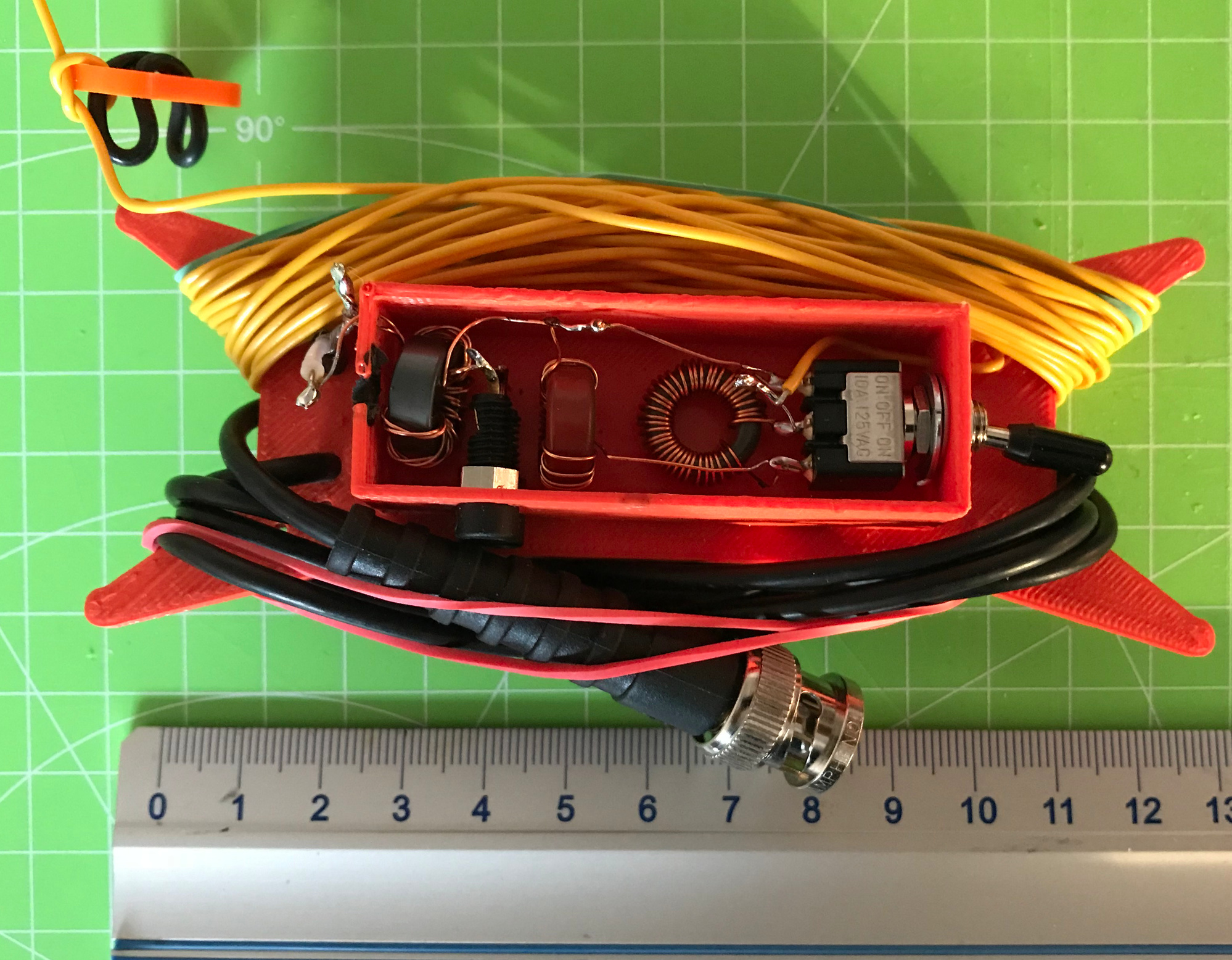
Hi all, in the meantime, I built a variant of the N2CX design. The main differences are:
- I use T50-2 toroids instead of T68-2 with 0.4 mm magnet wire. I think it won’t make a big difference and I did not have T68s at hand.
- I added a small common mode choke between coax and feedpoint, made from an FT50-43 and 11 turns of two twisted wires of 0.4mm magnet wire (similar to the “Pico Balun” from SOTAbeams).
- Instead of a PCB as a base, I used a 3D-printed case from earlier antenna experiments; it is basically similar to the winder from the Packtenna, but with a small rectangular case for components.
- I used Heinz’ proposal of a single SPDT ON-OFF-ON switch instead of two simple switches.
- As for the radial/counterpoise, I will use resonant, elevated ones. I have not yet decided whether it will be a single one with a winder and markers for 40-30-20m, or three ones connected, with one resonant for each band. This can also be changed later, since there are two 2mm plugs for this.
- Instead of a bulky BNC connector, I directly attached 1m of RF174 with a BNC.
The inductors have 8.15 uH (40…41 turns) and 3.6 uH (25…26 turns), similar to the original design.
The link to the coax is a bit quick-and-dirty, because the enclosure is a bit too small for the parts; I will maybe draw a new one once the concept works in the field.
Attached, please find a few pictures.
Before I tune it, I have a few questions:
-
When tuning a vertical with elevated radials, what do you tune first - the radiator or the radial? Or first the radiator for resonance frequency and then the radials for minimal SWR / impedance match?
-
Since I am using carbon-fiber masts, which might detune the antenna a little bit (see the dedicated thread on this topic), I am thinking of deploying the antenna as a steep sloper, with the feedpoint maybe 1 m away from the bottom of the mast. Does anybody have experience with the effect on the radiation pattern of a slightly tilted vertical?
73 de Martin, DK3IT
5 Likes
Ok, but this is a bit difficult to handle if you want to use the radial length for fine-tuning if the type of ground requires this - one would eed to have three small winders at each end and make sure they do not tangle.
Martin
Interesting discussion about radials / radialpoises. I’m thinking I’m going to stick with the recommended 4x10’ radials for now, since it gave good performance in my case. But I’m really curious what it’s going to do on summits with very poor ground, i.e. rocky summits.
Seeing what you’re doing, @DK3IT, I think I might modify my connectors—instead of using the wingnuts, I’ll solder on some of those gold hobby connectors and cut the weight while adding simplicity. While I’m at it, I might glue on a 1:1 balun and direct-connect the RG-174. You’re full of brilliant ideas!
73,
Rex KE6MT
1 Like
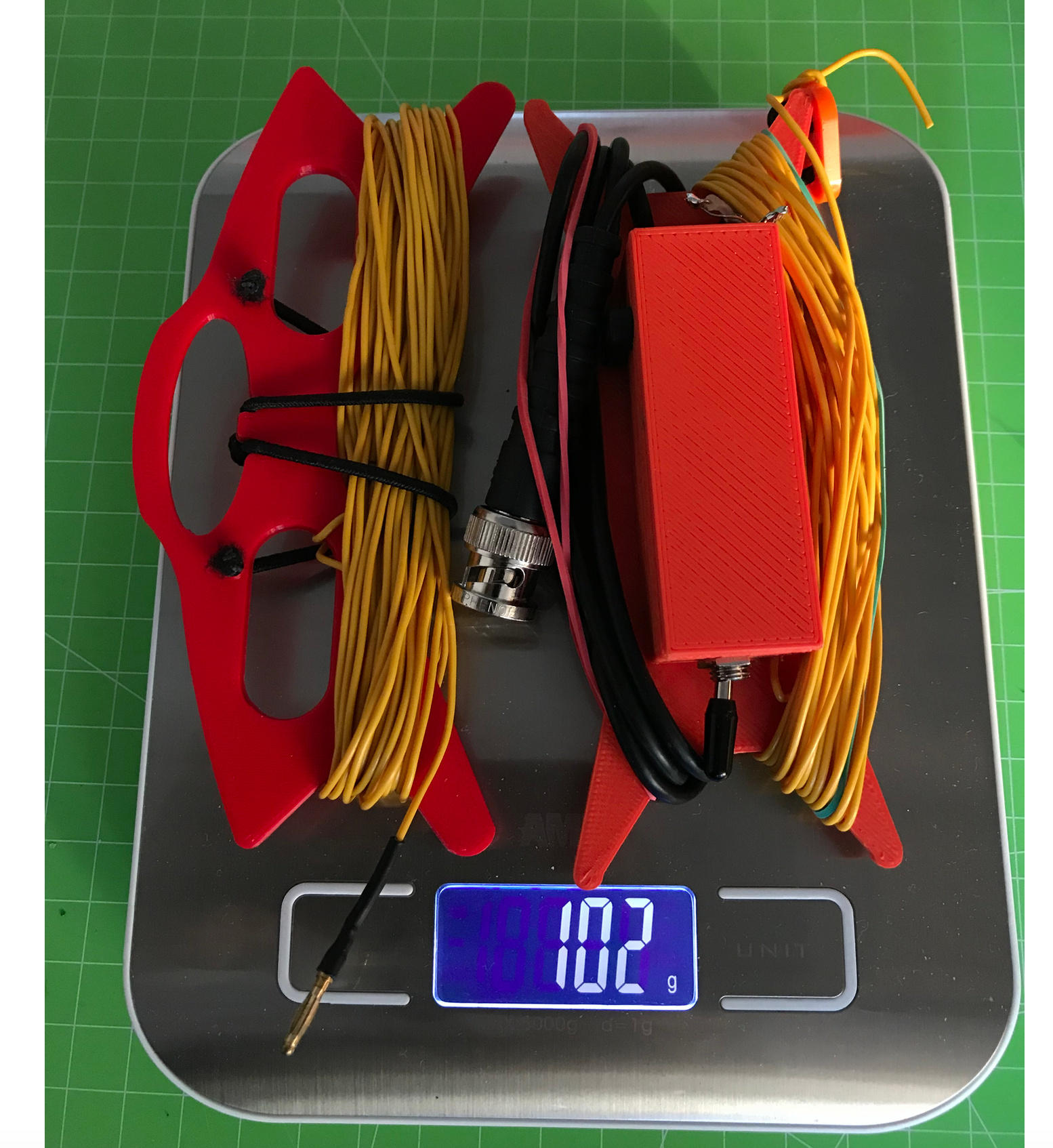
Nice fast work martin but I was crushed you did not break the 100 gram mark. Any way you can drill out the line winder and file down the box corners to get the weight down? The gram weenies will be very happy.
Great idea for the CMC
john ve3ips
1 Like