I have been using one of these for a couple of years and they work great and are so easy to make - de G4POP
I came across this from the Dutch hams websites. I am currently seeing if I can get the 80m-40-20-15-10 into my garden.
Looks a very good antenna. Unsure if it’s resonant on 17 and 12 or if auto atu is needed.
Hi Barry, If you’re interested in the antenna perhaps you should drop Joerg DJ4WD an email (kontakt@labshack.de) and ask him about 12 & 17m - I’m sure he’ll speak English.
For me the purchase price of €75 / €85 plus shipping seems a little steep.
73 Ed.
What I suppose is the following: This design uses the loading coil also as a simple trap, because for higher frequencies, the impedance increases. The effect of this depends on the position of the coil on the radiator - high current, a lot of attenuation, low current/high voltage, not so much. You can observe this effect when tuning and trimming such designs: The tuning of the 20m section before the coil requires the 40m section and coil to be attached, i.e. it is an imperfect trap.
I guess that one can find a position and inductance for the loading coil so that the SWR for 12 and 17 m will still be below 1:2.0.
The original design is analyzed here:
See in particular this image:
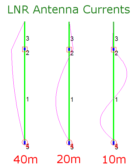
I am pretty optimistic that by varying the inductance and position a tiny little bit, you can get a good compromise for 17 and 20 on one hand and 12 and 10 on the other.
Martin
2 Likes
Hi Gents!
DK3IT is right, there is a sweat spot.
To garantee the success I simplified the construction manual in my article a little bit.
The antenna I sell in my shop is using another winding ratio (24:3) and method (W1JR crossover winding). And the already mentioned sweat spot is part of the magic sauce.
Today was nice sunny weather and I had a chance to do some quick measurements with spectrum analyzer and SWR bridge. I revised the SWR values a little bit (but still in the same ballpark) and uploaded two images:
http://www.dj4wd.de/images/SWR17m.jpg
http://www.dj4wd.de/images/SWR12m.jpg
HTH!
Cheers
Joerg DJ4WD
2 Likes
Hi Joerg, all:
Interesting!
BTW, the main reason I am not using my 40-20-10 design too frequently is that
- I miss 30m, because it is such a nice band full of classy CW operators and interesting propagation conditions and
- I would also love to have 17 and 15 m.
Has anybody thought of a variant of this design so that it works for 40 - 30 - 20 - 17 -15 m, i.e. all MTR-5B bands?
I guess one could
-
get 30m by adding a link at a reachable height in the lower section (but the question is whether the coil will be a good choice then, in terms of position and inductance)
-
get 17 and 15 m by adding two traps to the 20m section.
I assume tuning this could be a bit of work (likely 15 -> 17 -> 20 - > 30 -> 40 m), but then one would have a nice 11 - 12 m long vertical for five bands on the 10m mast.
Any ideas?
As said, I really loved this antenna, because of its good performance and because of the minimal space needed.
Martin
Hi
right now I’m working on a trapped endfed prototype.
40m, <2:1, approx.1,2:1
30m, <2:1, approx.1,3:1
20m, <2:1, approx.1,5:1
17m, <3:1, approx. 2,2:1
10m, <2:1, approx.1,5:1
Still not ready for the public and reproduction. 
Does this suit SOTA needs? 15m is missing.
Cheers
Joerg DJ4WD
I see. The Mountain Topper trx is using the bands 40/30/20/17/15m.
Maybe I can come up with something next spring.
When its ready I’m going to publish an article with construction guide again, so everyone can thinker by himself.
Cheers
Joerg DJ4WD
1 Like
Hi Joerg,
that sounds interesting! My main interest is finding a 5-band antenna that is at max 12 - 10 m so that it can be used as a vertical on a 10m mast.
If your design does not use a loading coil, then you should have a look at the 3-band EFHW by Heinz, HB9BCB:
His design is IMO the state-of-the-art in SOTA antennas, and pretty popular afaik.
17 and 15 m could be added by links to the first radiator segment; this is actually what I have on my list of projects.
Even a bit more elegant would be to make the end of the antenna at the rig / transformer side detachable so that you can shorten the 20m radiator part from the rig side. I took this idea from Brad, WA6MM. The 20m trap should also end the radiator for 17 and 15m, and you would not have to lower the mast to change to these two lower bands.
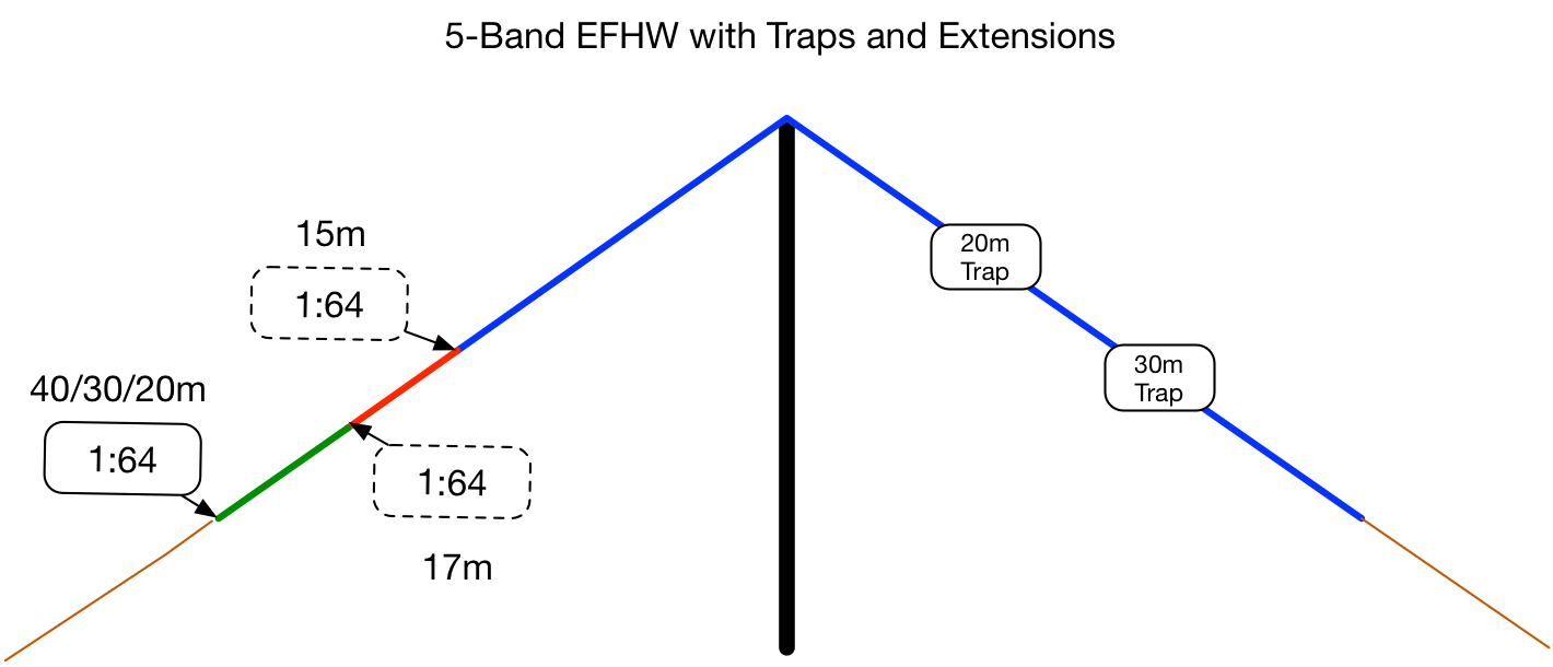
Attached, please find a few pictures of my proposal. Maybe Heinz and Brad can take a look with their expert eyes.
73 de Martin, DK3IT
1 Like
Hi Martin,
I just saw your latest post on this thread. My short/long adjustment mechanism was implemented because the traps reduced the effective bandwidth of my antenna. The short/long adjustment basically shifted the resonance 150-200 kHz so I could work both the cw & ssb portions of the 20 and 40m bands without needing a tuner. In doing that I found that the short adjustment lowered the VSWR on 17m so I could actually use that band as well. I haven’t studied or characterized that effect but now you have me interested in doing that!
The 20m trap will no longer act as a trap on 17m or 15m. I know K1JD has managed to build a trapped 5-band EFHW antenna (four traps). He has mentioned that the tuning gets substantially harder as you add more traps. Lots of interaction between the traps and iterations of adjustment. I’ve experienced some of that with only two traps! Perhaps some day I’ll get motivated to experiment more. But for now, I’m happy using my two trap EFHW antenna on 17,20,30, and 40m. I’m going to do a sweep across the hams bands with my analyzer on my current antenna…well, when the weather improves here!
73, Brad
WA6MM
Brad, how are you getting 4 bands with two traps? I would think you’d need three traps. Are you using a link?
Barry N1EU
Dear Brad,
thanks!
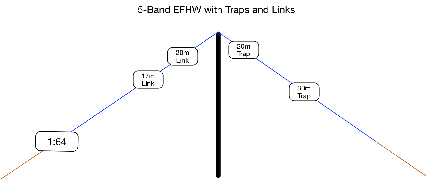
I already had a bilateral conversation (not a QSO, unfortunately, hi) about that with Heinz, HB9BCB. He uses links for 15 and 17 m and traps for 20 and 30 m.
I have now decided to use links for those as well, because the extensions at the endpoint of the antenna would be too long to be practical; one would have to take off roughly 1,5*0,95 = 1,425m for getting from 20 m to 17m, and another 95 cm for getting from 17 to 15m. This would mean repositioning the rig etc., so it is simpler to lower the pole a bit, reach out to the links and open/close them.
For others who want to try that design, I attach the plan. This is basically the antenna described by Heinz here: Trap EFHW and Coupler, plus the links for 17 and 15m.
By the way, Heinz’ design uses slightly bigger inductors and smaller capacitors than the tiny SOTAbeams traps. This reduces the resonant lengths a bit, which I find a plus. 16m is a handy length. What is really nice about this design is that it is pretty stable in terms of tuning - other than verticals, you can leave the tuner at home.
73 de Martin, DK3IT

The links on my POLYS #26 EFHW antenna wire are placed at 6.565m (21.06 MHz) and 7.71m (18.08 MHz).
Hi Barry,
I implemented a short/long adjustment mechanism at the feedpoint side of the antenna. That basically adjusts the antenna length about 29 inches (0.73m). I did that to be able to cover the entire 20 and 40m bands with a VSWR under 2:1. The beauty of it is that I can easily adjust it without collapsing the pole. Of course, I only needed to adjust it if/when I wanted to work SSB. What I also discovered is that the short adjustment (antenna 29 inches shorter) lowered the VSWR on 17m to an acceptable level. Perhaps you can call this adjustment mechanism a “link” ;-). Go to my QRZ page and scroll down until you see the diagram and associated VSWR plots.
Hi Martin,
Yes, links seem to make sense if you want 15m. It is interesting that I got 17m by just shortening the endpoint 0.73m. I wasn’t intentionally trying to tune it for 17m – it just worked out. These trapped EFHW antennas are certainly interesting the way everything interacts! And then you have antenna height and ground conditions that will have an effect on things. I’ve noticed that my VSWR will change when the wind bends my pole closer to the ground depending on activating in the treeline or on a rocky summit. I’m glad a now have a KX2 with internal tuner so I don’t have to worry so much about antenna resonance and such!
My traps reduced the length of the wire required (which is nice) but also reduced the 2:1 bandwidth. Not a big deal if you have a tuner or only work either CW or SSB. Or, just live with reduced power ;-).
73, Brad
WA6MM
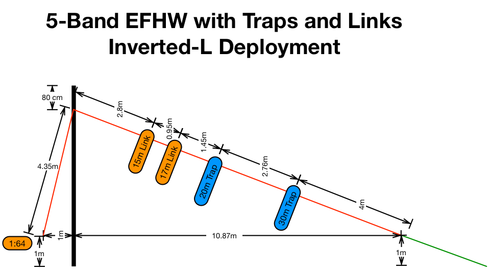
Hi all,
attached, please find a sketch of how the antenna looks like in an inverted-L deployment as inspired by Brad’s description on his QRZ page, WA6MM - Callsign Lookup by QRZ Ham Radio, this time with the links shown. I drew this while Heinz was drafting his reply, so likely, his values for the position of the links are closer to the truth. But you have to tune the antenna anyway. My initial lengths for the 3-band version are for SOTAbeams antenna wire and an inverted-V configuration at a 6m mast.
Martin
PS: I would expect that in particular on the short bands, the too narrow angle at the top would cancel out part of the RF energy. But I agree that an inverted-L is much handier in terms of deployment.
1 Like
Hi Gents
The next Funktelegramm, April 2018, features a 6 page article about my new EGA30 antenna. An end-fed antenna for 30/17/12m (WARC) with an overal length of 6,6m.
Main focus is the background of end-fed antenna design: how to calculate and solve the math for a cascaded end-fed antenna.
The article is for DIY hobbyists and there are also specific build instructions (value of the coils, length of all antenna segments, etcetera …) to build your own version:
• V.S.W.R: 30m: between 1:1,1 and 1:1,3
• V.S.W.R: 17m: between 1:1,2 and 1:1,7
• V.S.W.R: 12m: ≤1:1,1
But you can also tackle the math and calculate your own version with other bands …
Cheers
73 de Joerg DJ4WD
PS: If someone is all thumbs, this antenna is also available in my shop www.dj4wd.de … ![]()
3 Likes
Hi everyone,
hopefully necroposting is accepted here. I did not want to start a new thread for asking how to build one of the antennas mentioned here. My interest is a portable 40/30/20 antenna, which works without a tuner and on a 6m carbonfiber mast (Decathlon offers theses currently for the cheap).
I read through the great document linked by @DK3IT and also visited the QRZ.com profile of WA6MM.
I wondered about the materials required. SOTAbeams sells these microtrap kits, but they weren’t referenced here. I can get my hands, in Germany, on T44-6 and T44-2 toroids no problem, but it’s harder to find the mica capacitors. Would others work? Could I instead use SMD capacitor of comparable capacity? I am bit lost at that point ![]()
For the antenna wire, I mostly going to go for DX-Wire UL, since sotabeams is out of stock and I can’t find POLYS #26 in Germany.
1 Like
Gunnar,
A source for mica capacitors with a nominal voltage of 500 V could be
An alternative to Polys #26 could be the new micro wire sold by DX-WIRE (I have not yet held this wire in my hands).
73 gl, Heinz
1 Like
Hi Heinz,
thanks for your reply and the hint to the box73 store. I will check it out and order some from them 
The rest of the material I can source from reichelt.
Thanks for your detailed descriptions, also for the coupler.
73, Gunnar
EDIT: Found a source for my needs on ebay-kleinanzeigen
Please note the information provided by the manufacturer
“We do not recommend this wire for portable operation, DX-WIRE UL or FL is more suitable for this.”
73 Chris