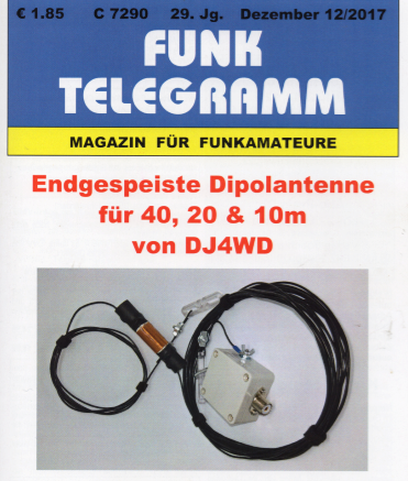
Possibly something of interest for SOTA use is the feature article in the latest (December 2017) “Funk Telegram” magazine. This is a design by DJ4WD with full details for self construction in the 4 page article. The design is interesting in that it uses a loading coil for operation on 40m and hence keeps the overall length more manageable at under 12m. The “EGA 40” antenna can be used on 40, 20, 17, 12 & 10m without an ATU. There’s also an 80/40m version.
The author also manufactures and sells the EGA40 antenna (€ 85 plus shipping) and details are on his website at http://www.dj4wd.de/ega40_en.html.
Very interesting! Could you probably summarize the design details for those who have no access to the FUNK TELEGRAMM, i.e. inductance and position of the coil? I would also be interested in how the resonance on 17m and 12 m is achieved without links - is that due to a clever choice of the loading coil in terms of position and inductance?
I use that antenna a lot, mostly as a vertical if I carry my 10m mast with me. Both for 20 and 40 m it has never let me down - will compare it to other designs by means of WSPRlite if time permits.
The only downside I see is that it lacks 30 m. I built an optional top piece for 30m but actually use it rarely. The EFHW with traps designed by Heinz HB9BCB is more convenient in that respect, but also 4 m longer.
BTW, I designed 3D-printable parts for the VK3YY antenna, which make for a very handy final product:
Hi barry,
Please refer to the website (http://www.dj4wd.de/ega40_en.html). In fact the Funk Telegramm article doesn’t mention 12m & 17m however the website - where a fully built antenna can be purchased gives the following table:
Yes, I saw the Web site and that’s why I’m asking. I don’t find the low SWR on 17M and 12M believable until I hear some explanation. I don’t see any traps and we don’t have harmonically related bands. Why is the antenna resonant on 17M and 12M?
I came across this from the Dutch hams websites. I am currently seeing if I can get the 80m-40-20-15-10 into my garden.
Looks a very good antenna. Unsure if it’s resonant on 17 and 12 or if auto atu is needed.
Hi Barry, If you’re interested in the antenna perhaps you should drop Joerg DJ4WD an email (kontakt@labshack.de) and ask him about 12 & 17m - I’m sure he’ll speak English.
For me the purchase price of €75 / €85 plus shipping seems a little steep.
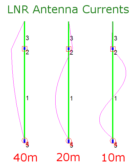
What I suppose is the following: This design uses the loading coil also as a simple trap, because for higher frequencies, the impedance increases. The effect of this depends on the position of the coil on the radiator - high current, a lot of attenuation, low current/high voltage, not so much. You can observe this effect when tuning and trimming such designs: The tuning of the 20m section before the coil requires the 40m section and coil to be attached, i.e. it is an imperfect trap.
I guess that one can find a position and inductance for the loading coil so that the SWR for 12 and 17 m will still be below 1:2.0.
The original design is analyzed here:
See in particular this image:
I am pretty optimistic that by varying the inductance and position a tiny little bit, you can get a good compromise for 17 and 20 on one hand and 12 and 10 on the other.
DK3IT is right, there is a sweat spot.
To garantee the success I simplified the construction manual in my article a little bit.
The antenna I sell in my shop is using another winding ratio (24:3) and method (W1JR crossover winding). And the already mentioned sweat spot is part of the magic sauce.
BTW, the main reason I am not using my 40-20-10 design too frequently is that
I miss 30m, because it is such a nice band full of classy CW operators and interesting propagation conditions and
I would also love to have 17 and 15 m.
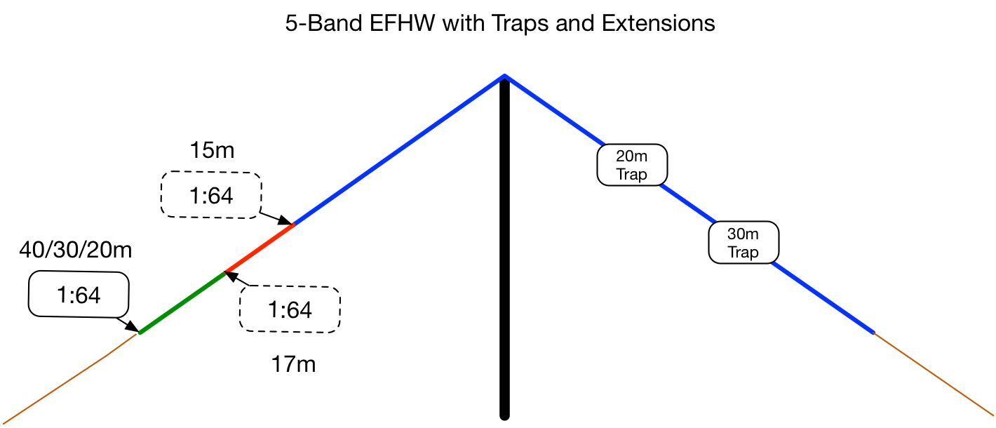
Has anybody thought of a variant of this design so that it works for 40 - 30 - 20 - 17 -15 m, i.e. all MTR-5B bands?
I guess one could
get 30m by adding a link at a reachable height in the lower section (but the question is whether the coil will be a good choice then, in terms of position and inductance)
get 17 and 15 m by adding two traps to the 20m section.
I assume tuning this could be a bit of work (likely 15 -> 17 -> 20 - > 30 -> 40 m), but then one would have a nice 11 - 12 m long vertical for five bands on the 10m mast.
Any ideas?
As said, I really loved this antenna, because of its good performance and because of the minimal space needed.
right now I’m working on a trapped endfed prototype.
40m, <2:1, approx.1,2:1
30m, <2:1, approx.1,3:1
20m, <2:1, approx.1,5:1
17m, <3:1, approx. 2,2:1
10m, <2:1, approx.1,5:1
Still not ready for the public and reproduction.
Does this suit SOTA needs? 15m is missing.
I see. The Mountain Topper trx is using the bands 40/30/20/17/15m.
Maybe I can come up with something next spring.
When its ready I’m going to publish an article with construction guide again, so everyone can thinker by himself.
Hi Joerg,
that sounds interesting! My main interest is finding a 5-band antenna that is at max 12 - 10 m so that it can be used as a vertical on a 10m mast.
If your design does not use a loading coil, then you should have a look at the 3-band EFHW by Heinz, HB9BCB:
His design is IMO the state-of-the-art in SOTA antennas, and pretty popular afaik.
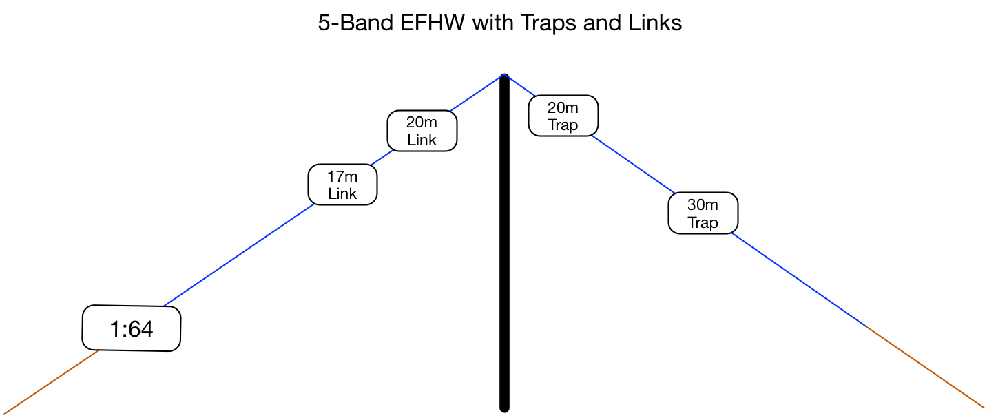
17 and 15 m could be added by links to the first radiator segment; this is actually what I have on my list of projects.
Even a bit more elegant would be to make the end of the antenna at the rig / transformer side detachable so that you can shorten the 20m radiator part from the rig side. I took this idea from Brad, WA6MM. The 20m trap should also end the radiator for 17 and 15m, and you would not have to lower the mast to change to these two lower bands.
Attached, please find a few pictures of my proposal. Maybe Heinz and Brad can take a look with their expert eyes.
Hi Martin,
I just saw your latest post on this thread. My short/long adjustment mechanism was implemented because the traps reduced the effective bandwidth of my antenna. The short/long adjustment basically shifted the resonance 150-200 kHz so I could work both the cw & ssb portions of the 20 and 40m bands without needing a tuner. In doing that I found that the short adjustment lowered the VSWR on 17m so I could actually use that band as well. I haven’t studied or characterized that effect but now you have me interested in doing that!
The 20m trap will no longer act as a trap on 17m or 15m. I know K1JD has managed to build a trapped 5-band EFHW antenna (four traps). He has mentioned that the tuning gets substantially harder as you add more traps. Lots of interaction between the traps and iterations of adjustment. I’ve experienced some of that with only two traps! Perhaps some day I’ll get motivated to experiment more. But for now, I’m happy using my two trap EFHW antenna on 17,20,30, and 40m. I’m going to do a sweep across the hams bands with my analyzer on my current antenna…well, when the weather improves here!
Dear Brad,
thanks!
I already had a bilateral conversation (not a QSO, unfortunately, hi) about that with Heinz, HB9BCB. He uses links for 15 and 17 m and traps for 20 and 30 m.
I have now decided to use links for those as well, because the extensions at the endpoint of the antenna would be too long to be practical; one would have to take off roughly 1,5*0,95 = 1,425m for getting from 20 m to 17m, and another 95 cm for getting from 17 to 15m. This would mean repositioning the rig etc., so it is simpler to lower the pole a bit, reach out to the links and open/close them.
For others who want to try that design, I attach the plan. This is basically the antenna described by Heinz here: Trap EFHW and Coupler, plus the links for 17 and 15m.
By the way, Heinz’ design uses slightly bigger inductors and smaller capacitors than the tiny SOTAbeams traps. This reduces the resonant lengths a bit, which I find a plus. 16m is a handy length. What is really nice about this design is that it is pretty stable in terms of tuning - other than verticals, you can leave the tuner at home.