I hope my microphone development may be of use to other users.
To extend my activation of SOTA summits, a couple of years ago, I purchased an FT857. I was disappointed to find that the supplied MH-31 fist mike weighed in at 200grams and took up my whole hand, I only had one remaining hand to hold the logbook, hold a pencil and twiddle whatever needed twiddling! What I needed was an electret, lapel or headset boom mike.
A visit to the “pound shop” provided me with 2 headsets, each with a boom mike. This may sound extravagant but this is the cheapest way to purchase electret microphone capsules!
A search on the web revealed the simple circuit needed to power the electret and recover the audio signal. Then I noticed that the Yaesu MH31 microphone has two audio positions, 1 and 2. More research unearthed that in position 1, the microphone is wide banded and intended for use with Japanese voices where the low frequencies in the “tones” convey information. For western voices position 2 is more appropriate. In this position a simple high pass filter with Fc of about 1kHz is included to condition the audio, particularly for ssb use. Additionally this filter works well as a wind noise attenuator.
The microphone plug on both the 817 and 857 is the 8 pin RJ45, widely used in ethernet installations. The standard electret capsule includes the microphone and a fet to provide a low impedance audio output. It does however requires a supply voltage of about 3 Volts. After a bit of experimentation I found I could select the filter components both to form the filter and also add bit of attenuation to match the audio requirements of the rig. Both the 817 and 857 microphone sockets provide a DC supply at 5 Volts that will power the electret. I felt a plan coming together.
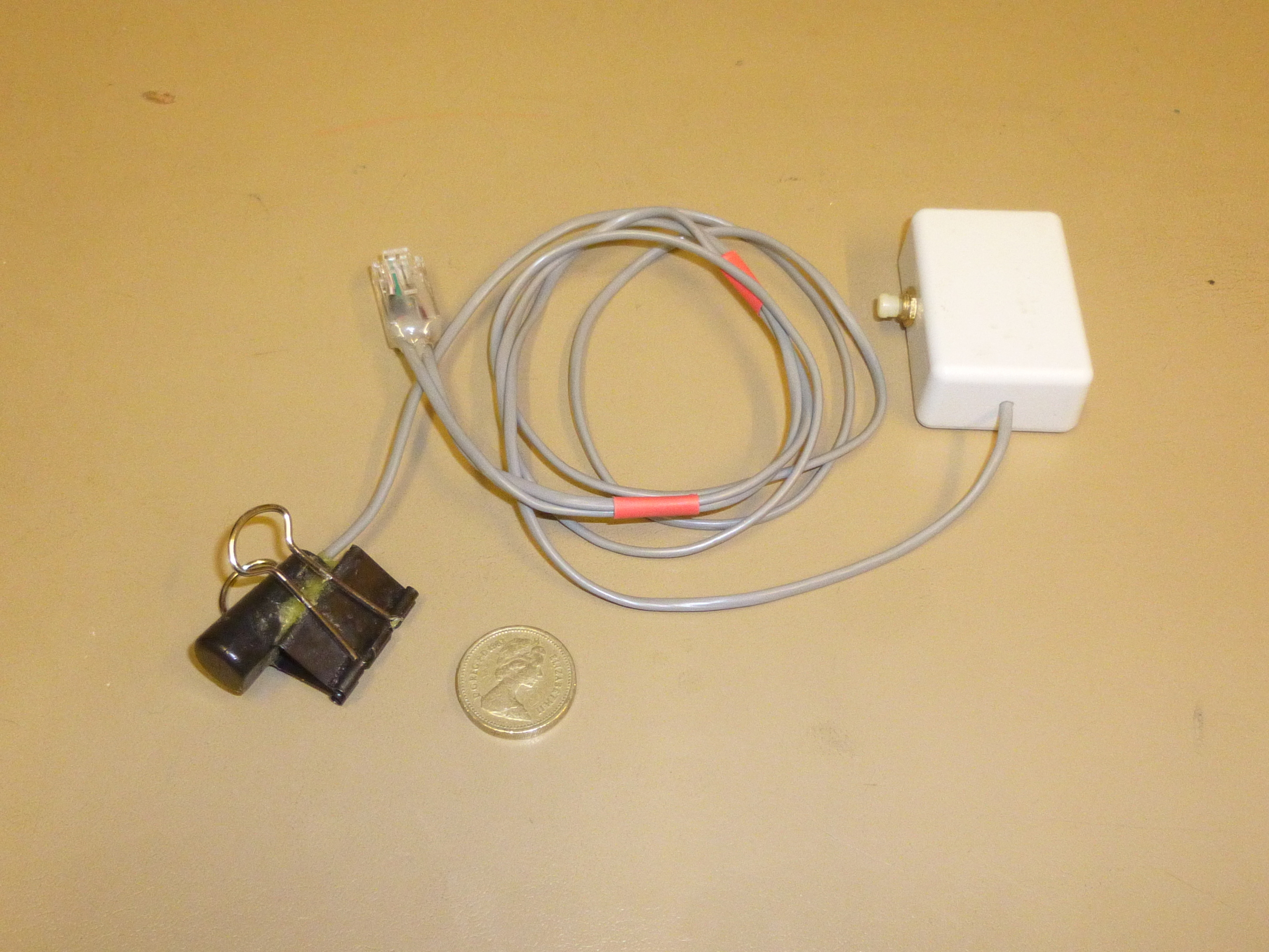
After a bit of practice, I could build the components for the filter and electret power supply into the RJ45 plug. The capacitor is a 4.7uF 16Volt Tantalum bead and the two resistors are 1/8 Watt. Coming off the plug is the lead to the PTT, a miniature screened cable, this is taken to a small box containing a small microswitch. A second screened cable goes to the electret capsule. I kept these two earths separate, they connect to different parts on the rig PCB, I did not want to create earth loops. Both screened cables were Maplin supply.
Construction of the plug filter components is fiddly and if necessary could be built elsewhere.
My build plan was as follows:
Cut 5 pieces of Insulation Displacement Cable (IDC) from a piece of ethernet cat 5 cable
Solder the PTT screened cable to 2 IDC wires
Solder 3 IDC wires to the 2 resistors and 1 capacitor
Check the wiring against the circuit diagram, then check it again
Cut the IDC wires to the correct length
Carefully push the 5 IDC wires into the plug
Check that the wires are definitely in the correct troughs and any bare wires are not touching, check them again
Taking care not to squash the pug retaining tang, use the RJ45 plug crimping tool (the wrong way round) to crimp the wires (we do not want to implement the cable strain clamp)
Set the plug in the bench vice and flood the cable entry end with Aradite or similar epoxy resin
When the adhesive has set check the plug connections using a multimeter on the Ohms setting. Confirm that pins 2, 3, 4, 5, 6 return the expected readings. If it is wrong, start again!
Now is the time to connect the electret (observing polarity) and the PTT switch.
The Acid test comes next, Plug the mike plug into the rig, connect a dummy load and power it up, If an HF oscilloscope is available, observe the SSB waveform and adjust the mike gain to get the expected envelope waveform, compared to a carrier. If this is not available ask a friend to monitor the audio on FM and SSB, adjust the mike gains as appropriate. My experience on the hills has been very satisfactory, the tie clip version weighs in at 40grams and audio reports have been complementary.
You now have a “hands free” lapel or boom microphone with headphones and a smile on your face from an expenditure of £2 plus a few items from the junk box.
Builder takes full responsibility for implementation.
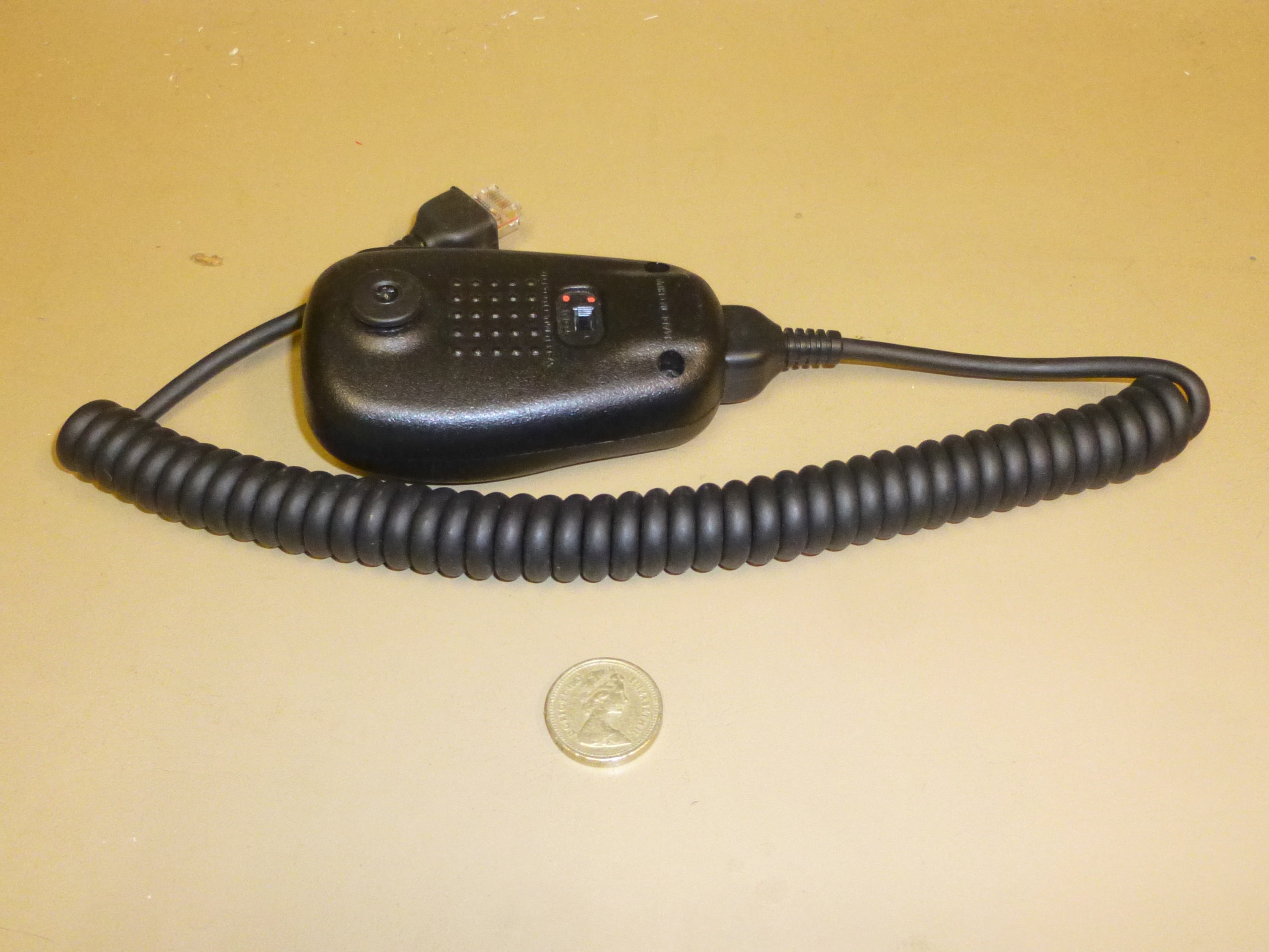
Yaesu MH-31 Fist mike
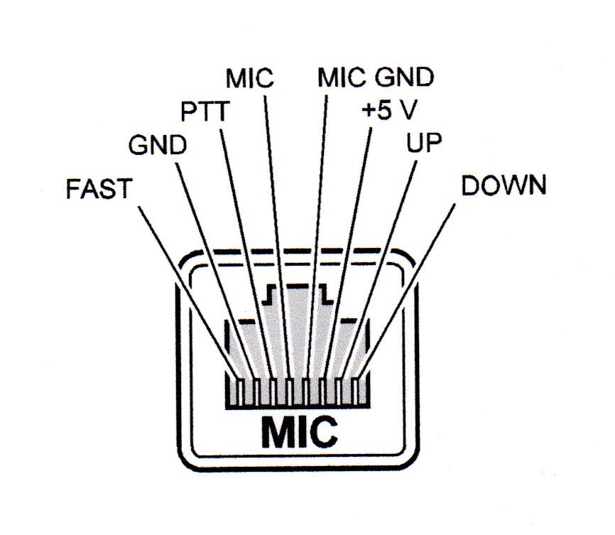
Microphone plug pinout looking at front panel
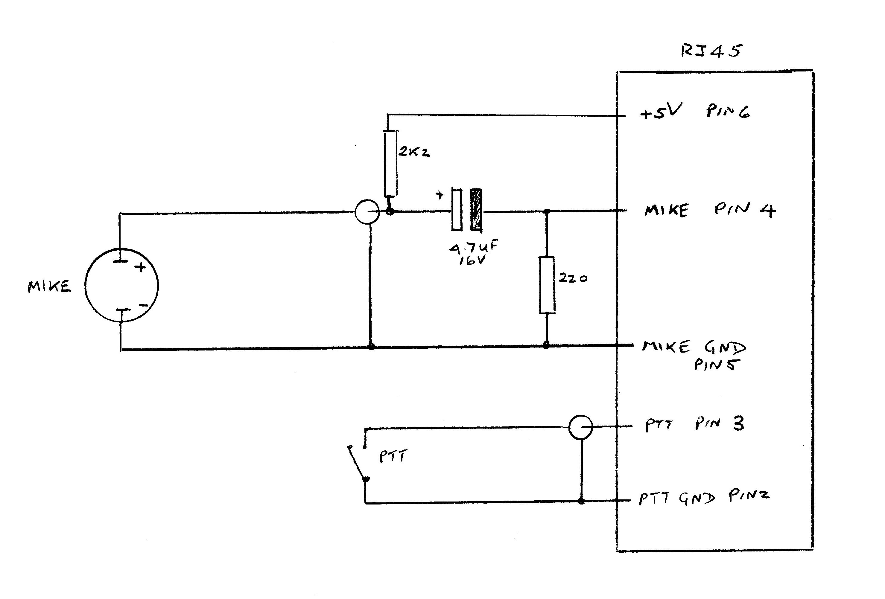
The HP filter and signal level conditioning circuit
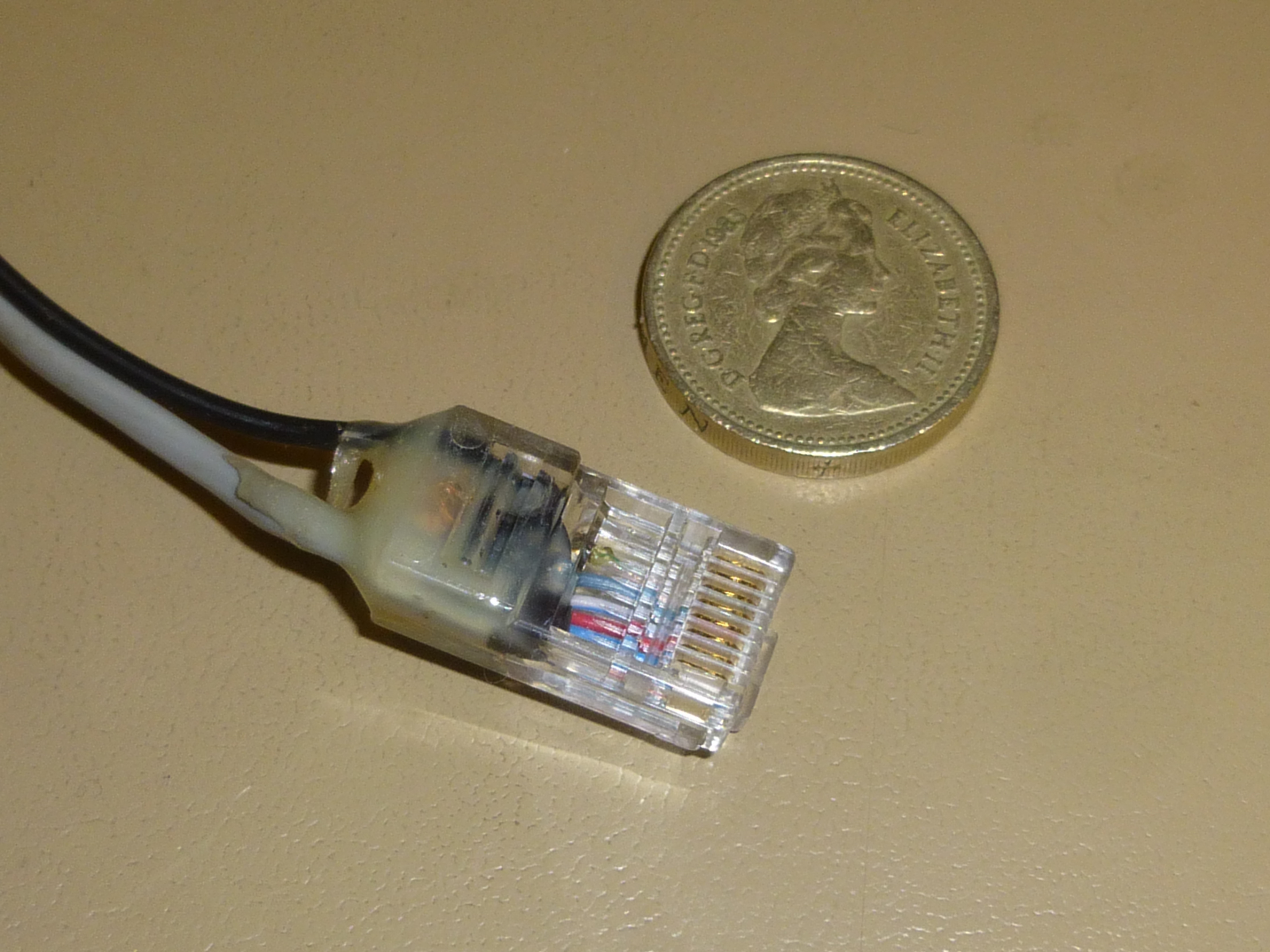
The RJ45 plug with components
Lapel mike
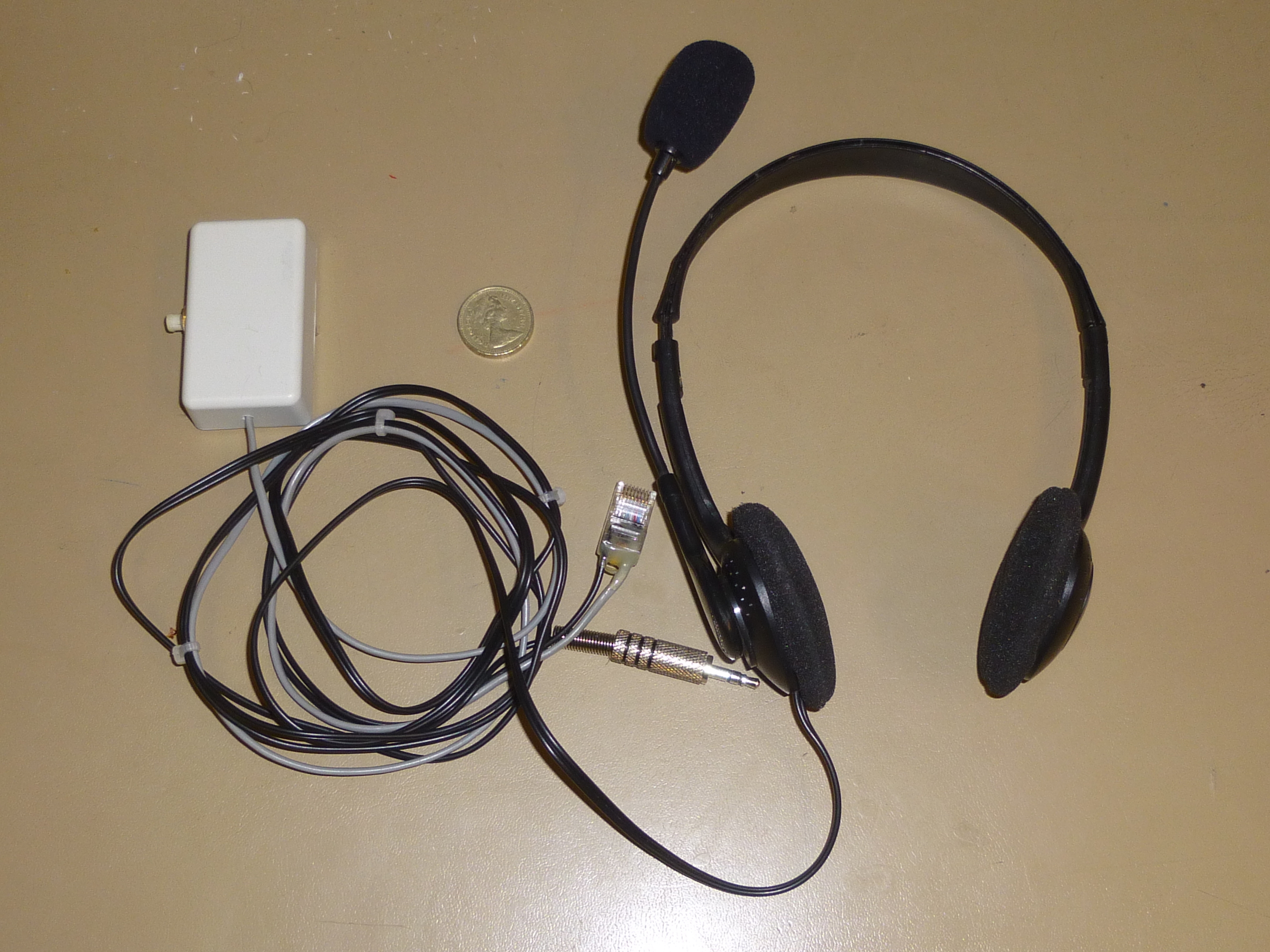
Boom Mike
