Hi…I’ve followed many of the EFHW Transformer postings…and I have 3 questions I don’t recall seeing information explaining when to use one of the 3 toroid options…
I see T-6 (yellow) seems to be the predominate variety…but I also see postings for T-2 (red)…
What scenarios make sense to pick T-6 (yellow) vs. T-2 (Red) toroid?
– 1-Frequency?
– Multi-Frequency with a variable capacitor (ex: 17m-40m) ?
– QRP vs. QRO ?
I think understand mix FT-43 is for Broadband with a fixed capacitor - correct?
What are the scenarios to decide on a Toroid-Size? Are there generally ‘safe’ sizes for a given transmit power and mode (data, CW, SSB)?
Jim,
I am by no means an expert but here are a few things I have learned on this.
An FT-140 size will work for up to 100W based on what I have built. The mix used was 31.
An FT-240 size is more suited for 100W as the cores in end fed antennas seem to warm up with higher power moreso than a 1:1, 4:1 or 9:1. This is Ham-Lore I have heard from a couple sources. Also supported by the size core used in several commercial products.
Based on what I have seen by others playing with EFHW’s is that mix 43 performs better in this use than mix 31.
Capacitor value is 100 - 150 pF at 1kV. MIca works best, changed my original to Mica and found it improved bandwidth vs the ceramic disc I had initially used.
I do believe there is a certain amount of voo doo involved in making a working EFHW transformer. Things that can bite you - large differences in diameter of wire for transformer and antenna. A tip passed on via my reading of other’s findings. As with any balun/coil - winding space and those errant ‘half turns’ that can change impedance ratio.
I am using a FT140-43 core with a 1:49 impedance ratio (2 primary turns + 12 turns) and 100 pF, 1kV parallel to the primary winding with good results. Do not try 3 primary turns +18 turns which of course gives the same ratio of 7.
With a 2.7-kOhm load resistor the transformer shows a SWR < 1.1 up to 14 MHz. Insertion loss is about 1 dB. The transformer feeds a Trap-Endfed for the 20, 30 and 40m band.
I think understand mix FT-43 is for Broadband with a fixed capacitor - correct?
Kinda, but not really. For this application you’ll want to use a type 61 mix. For more information I’d recommend this post from the groups.io antennas group (you may have to join) Re: End fed wires
I’m also using a FT 140-43 with 1mm enamelled copper wire. Turns ratio is 24:3, transformation ratio is 64:1.
It works okay on the bands 7, 10, 14 MHz, but from the data sheet you can see that FT -43 mix is not really suitable. Thus, building an UnUn with FT -61 mix is on my list already for some time.
Amidon, a North American ferrite supplier, has a free booklet that describes all the different powdered iron and ferrite materials, the range of frequencies they cover, the formula for calculating the power they will handle, recommendations for broad-band as opposed to tuned circuit use, and probably much, more.
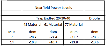
Today I thought I’d give it a try and made some Near Field power measurerments with various ferrite materials for my Endfed Baluns. All baluns are type 1:49. Transmitting power 3 W.
The antenna was set up in the garden, a Metro VNA served as powermeter at 15 m distance. Checking for loss in ferrite material should be possible also under nearfield conditions - or am I wrong?
Here are the results (the power levels are given in - dbm, so the lowest negative value is the best):
As VA7JBE and VE6IXD aleady stated, material 61 seems to be a little better, but not as much as I thought. I also tried 77 material, which turned out to be not suitable (although I found information that it could also be used for broadband applications).
At the end I compared with my linked dipole (same height, same position, always one antenna on the mast and the other on the ground). Very surprising the value on 14 MHz. The dipole is 3 dB weaker than the “lossy” endfed. I have to check that again.
Has anyone else got experience in testing antenna efficiency in the near field?
I would be happy if someone could comment on that.
On the assumption that the Ununs considered have a different reactance (due to their different ferrite mix), the transmission power (3 W) should be measured and adjusted at the input of the Unun.
Was this the case or was the transmit power of 3 W simply set on the TRX?
The transmit power was set at the KX3. All Baluns, when measured with a 2k7 load had an SWR less than 1.5:1. Also the SWR with the antenna (measured at the KX3) always was below 1.5:1.
It probably would be better to measure power and SWR at the input of the Balun.
Today I did some rough power measurements with two Baluns in a back to back configuration. Input power was 10 W. Frequencies at 7 / 10 /14 MHz
The results are:
Material 43: output power loss per balun was 1.5 / 1.5 / 1.75 W. Material 61: output power loss per balun was 0.5 / 0.5 / 0.75 W
So, as stated before, Material 61 seems to be quite superior to material 43.
When on a summit the receiving station might not notice much of a difference in the signal strengh whether you are transmitting with 8.5 or 9.5 watts instead of 10.
I would be glad the hear from other hams and their experience
Check out Owen Duffy on internet, he is clued up with end fed half waves
Theirs also a Facebook group Steve Ellington, He is clued up on EFHW
This info taken from their
Ft 240-43 is commonly used, any size below this equals a lot higher losses
31 and 61 mixes not good something to do with permeability
52 mix best, three times the price though
Larger the toroid lower the losses
Hi Peter,
I did the same with two Baluns in a back to back configuration. Using FT140-43 with 2 primary turns and 100pF parallel and 15turns secondary.
I can’t find an actual online calculator that will come up with the numbers. He does the math and shows screenshots of calculations but I can’t find where he provides an actual online calculator.
One pointer I can take away from Duffy’s site is that a single FT82-43 core may be insufficent to handle 12W cw from my KX2. He states that “max continuous average power” for a single FT82-43 EFHW xfmr in free air is 2.7W, but not exactly sure how to translate that for cw and xfmr in an enclosure but it would seem to be dangerously low for running 12W cw.