DC-DC Step-Up Converter with Filters for MTR and other QRP Rigs

Hi all,
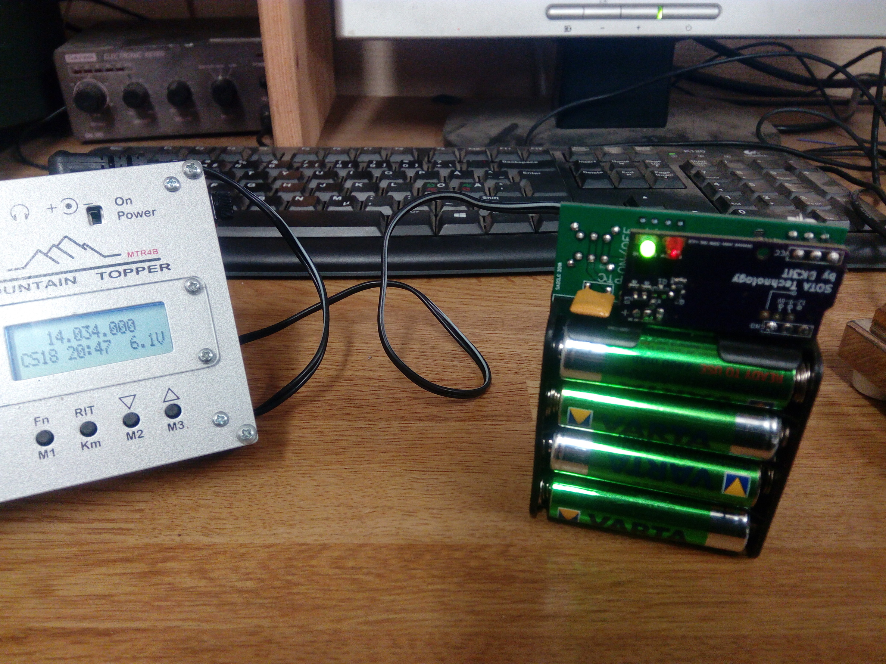
Mountain Toppers and other popular QRP rigs need 12 V DC to produce full 5 W output. Most people either use combination of cells (e.g. 8 x 1.5 V batteries, 10 x 1.2 V NiMH cells, 2 - 3 LiPo cells, etc.) for this purpose. This has two problems, however:

  1. Because the cell voltage has quite a range during the discharge cycle, you have to factor in some safety buffer for fully charged cells and their higher voltage (e.g. 3 x Lipo can have 3 x 4.3 → 12.9 and more when fully charged).

  2. You get full voltage and thus full 5 W power only at the beginning of the discharge cycle.

DC-DC converters are one way of handling this, because they can convert DC voltages from low to high voltage (“boost converter”), high to low voltage (“buck converter”) or either way (“buck-boost converter”).

The problem with such DC-DC converters is that they are prone to cause EMI due to their high switching frequencies and fast transients. Thus, many ham radio operators hesitate to use them near sensitive HF receivers.

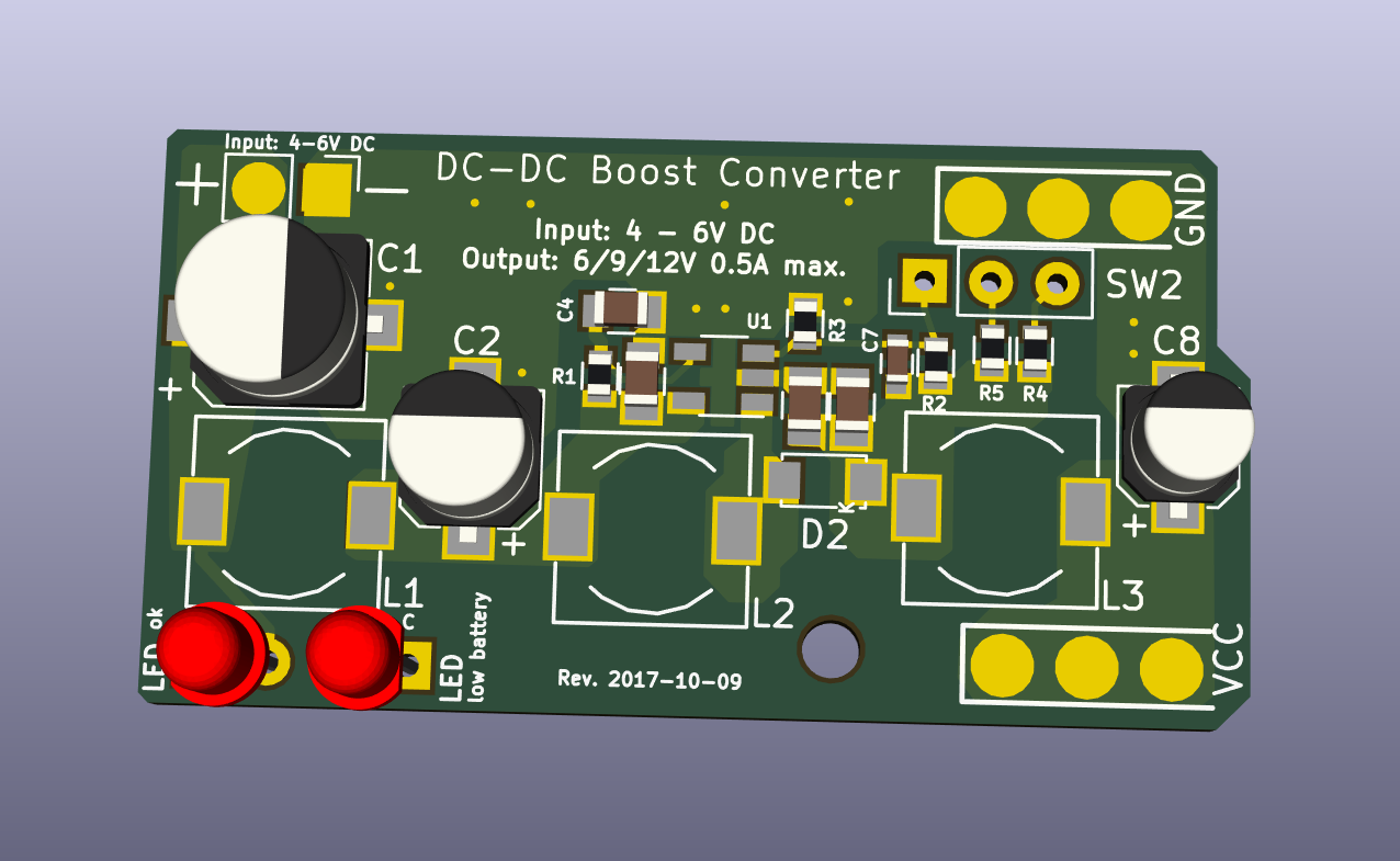
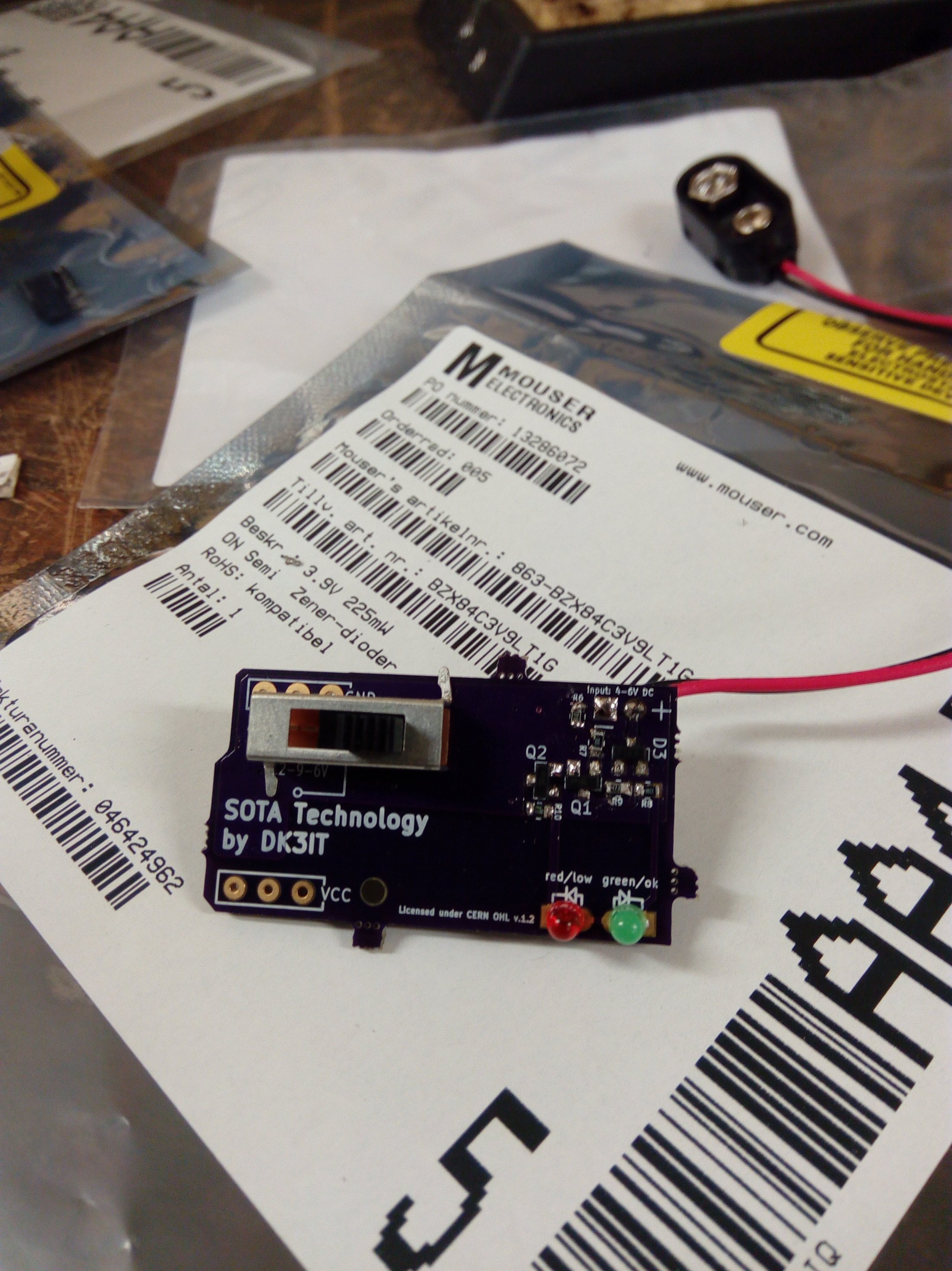
In order to solve that problem, I designed a DC-DC boost converter with highly effective input and output filters, specially targeted at QRP rigs like the MTR series.

The output voltage is switchable to 6, 9 or 12 V, and the output current can be up to 500 mA, depending on the ratio of input to output voltage. This allows operating with 1, 2.5 and 5 W with a MTR or similar transceiver.

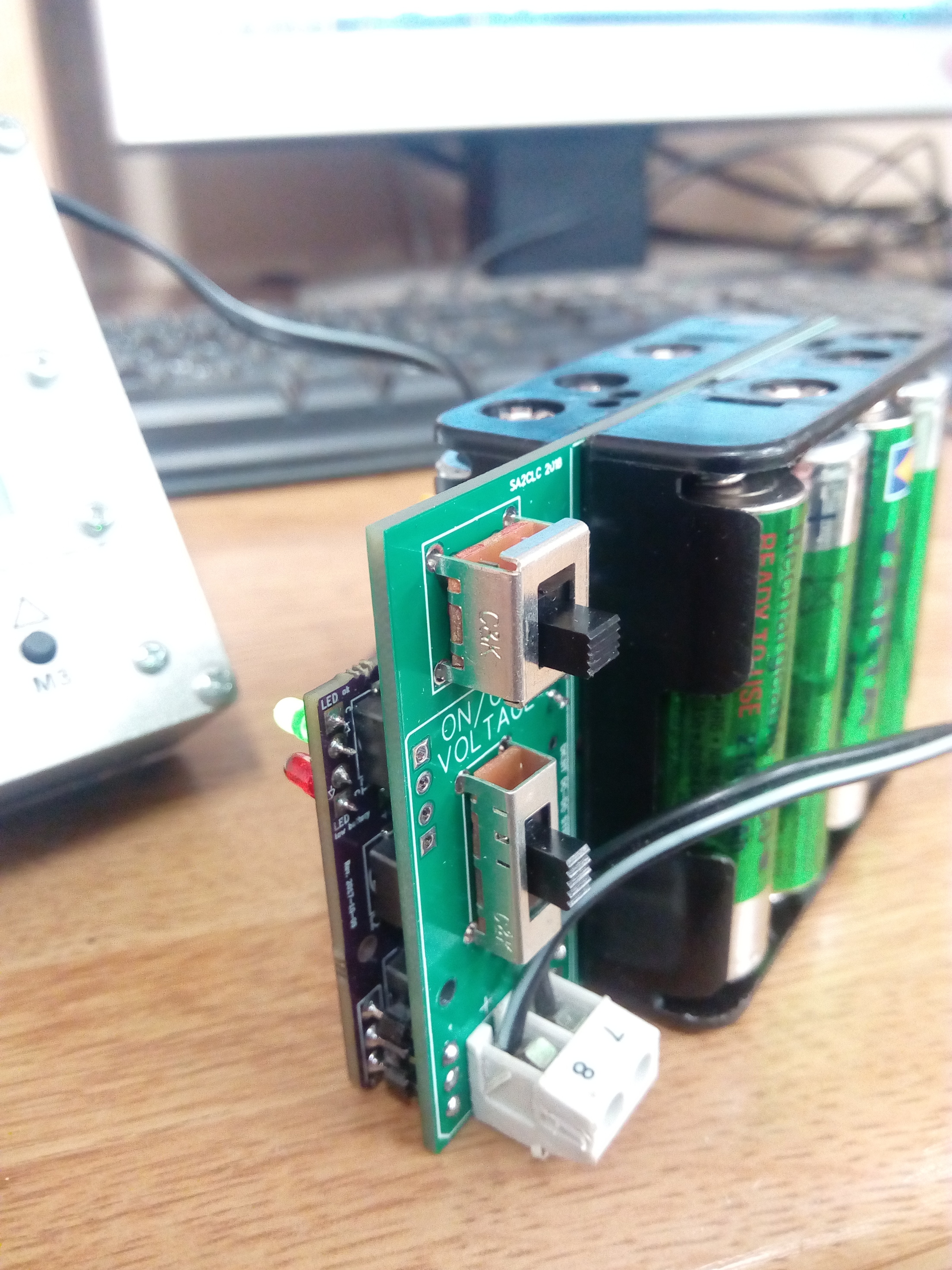
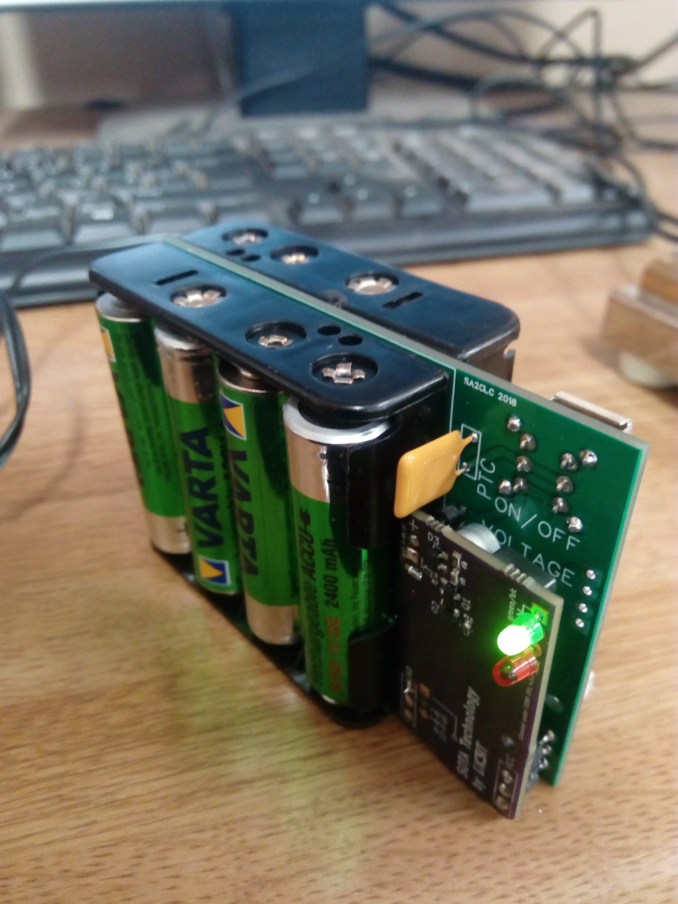
It is meant to be used with either 4 NiMH cell packs (e.g. AA) or 2 LiPo cells.

The circuit also contains a low battery indicator that can be configured to a warning at 3.9 (4 x NiMH) or 6.2 V (2 x LiPo).

The whole project is available as Open Hardware at

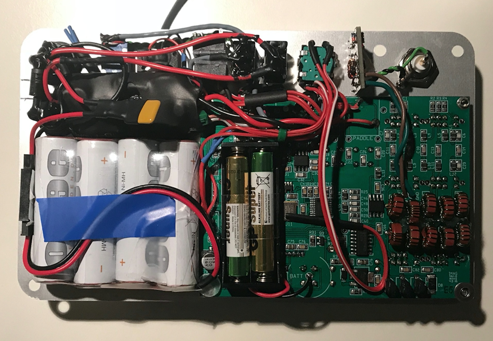
I assembled and tested a first prototype, and it works like a charm.

As usual, the PCBs can be ordered from OSH Park:
https://oshpark.com/shared_projects/79qs1gwU

The part list is included in the Github repository as an Excel file:
https://github.com/mfhepp/gobox-power/raw/master/hardware/go-box-power.xlsx

Same holds for the schematics:

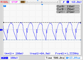
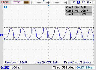
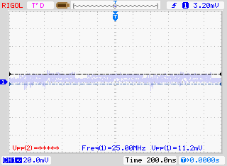
The output is really clean:

Maybe you find this useful for your own projects.

73 de Martin, DK3IT

9 Likes

Nice work Martin. However, I’m slightly confused as the PCB states (twice) that the input Voltage range is 4-6 Volts but your LiPO low voltage warning is at 6.2 Volts.

Hi Richard,
the reason that the PCB states an input voltage of 4 - 6 V is that I originally designed it for the use with four NiMH cells, and that the use with 2S LiPos is a mod I added to the design later on. The only actual constraints on the input voltage are that it must not be higher than the output voltage, because it is a step-up converter IC (Semtech SC4503, datasheet: Find Product Documentation).

The only thing that happens if the input voltage is higher or very close to the output voltage is that the output voltage will become unstable, because the regulator will try to use a pulse-width that is smaller than technically possible.

Thus, when used with a 2S Lipo configuration, one has to omit the 6V option (which I found handy for 1 W operation, mainly for tuning the Elecraft T1 with minimal load on the final transistors of the rig).

73 de Martin, DK3IT

Today, I compared the input and output ripple and noise of the new design with a standard Pololu DC-DC converter, which uses the exact same IC (and which I have built into my previous GoBoxes).

Attached, please find the measurements.

One can see that the ripple and noise at the output is almost 25 times (280 mVpp vs. 11.2mVpp), i.e. 14 dB higher than with my new design with filters. It might actually be even better, since I suspect that the remaining noise in my measurement might have been rather EMI from my lab environment.

On the input, the effect is a bit lesser with 180 mVpp vs 66 mVpp (4.3 dB). The exact effect will depend on the internal resistance of the supplying battery and other factors. Very sensitive components (e.g. AF amplifiers) are better connected to the output of this (and mostly: any) DC-DC converter, even if that requires an additional LDO to reduce the voltage again.

But one can sum up that the extra effort for the input and output filters makes sense.

73 de Martin, DK3IT

Pololu U3V12F12 Output Ripple at 8.2V input, 120 mA Load:

Pololu U3V12F12 Input Ripple at 8.2V input, 120 mA Load:

I have been asked in private whether this DC-DC converter is actually suitable for an MTR-3B and MTR-5B, because those draw ca. 560 mA at 5 W, and the PCB says the maximum load was 500 mA.

Short answer: Yes, no problem, both with 4 x AA NiMH cells and 2S Lipo cells.

Long answer: First of all, the critical value is not the output current, but the input current, which roughly depends on the ratio of output vs input voltage times the output current, minus the conversion losses.

If we assume a 90% efficiency, a load of 600 mA, and output voltage of 12 V and an input voltage of 6 V, then the input current is approximately

12/6 * 1/0.9 = 1.33 A

The exact formula is a bit more complicated and given in the SC4503 datasheet at

Now, the maximum input current is specified as minimally 1.4 A, typically 1.9 A, and maximally 2.5 A. So 1.4A is really on the safe side. A high input current has the following two effects:

  1. If the switch current exceeds 1.9A (the typical current-limit), then the current-limit comparator will set the latch and turn off the power transistor.
  2. The IC will heat up a bit. Should the temperature exceed 155 °C, there will be a thermal shutdown. Once the chip will have cooled down by 10 °C, it will resume operation.

So in worst case, the circuit will shutdown if it gets too hot, but in nine months of operating on a daily basis with this set-up, I have never experienced problems.

Most NiMH cells stay above 1.2 - 1.1 V per cell for the biggest part of their discharge cycle, so a 4 cell block will have more than 4.4 V almost all of the time.

Here is a computation of the maximum output current you can draw in the 12V setting. The first value is for the very conservative 1.4A limit, the second for the typical 1.9 A input current limit.

4.0 V : 0.4245A / 0.5761A
4.2 V : 0.4474A / 0.6071A
4.4 V : 0.4702A / 0.6381A
4.6 V : 0.4931A / 0.6692A
4.8 V : 0.5160A / 0.7002A
5.0 V : 0.5388A / 0.7313A
5.2 V : 0.5618A / 0.7624A
5.4 V : 0.5847A / 0.7935A
5.6 V : 0.6076A / 0.8246A
5.8 V : 0.6305A / 0.8557A
6.0 V : 0.6535A / 0.8869A
6.2 V : 0.6764A / 0.9180A
6.4 V : 0.6994A / 0.9492A
6.6 V : 0.7224A / 0.9804A
6.8 V : 0.7454A / 1.0116A
7.0 V : 0.7684A / 1.0428A
7.2 V : 0.7914A / 1.0741A
7.4 V : 0.8145A / 1.1053A
7.6 V : 0.8375A / 1.1366A
7.8 V : 0.8606A / 1.1679A
8.0 V : 0.8836A / 1.1992A
8.2 V : 0.9067A / 1.2305A
8.4 V : 0.9298A / 1.2619A
8.6 V : 0.9529A / 1.2932A
8.8 V : 0.9760A / 1.3246A
9.0 V : 0.9992A / 1.3560A
9.2 V : 1.0223A / 1.3874A
9.4 V : 1.0455A / 1.4188A
9.6 V : 1.0686A / 1.4503A
9.8 V : 1.0918A / 1.4817A
10.0 V : 1.1150A / 1.5132A

You can see that:

  1. Up to ca. 4.4 V, it is safe to draw 600mA (in particular if the duty cycle is only 50% as in a CW rig). Below that, you should switch to 9V / 2.5W.
  2. A 2S Lipo configuration can provide up to 0.6764A (very conservative) / 0.9180A (typical) at the cell voltage of 3.1V, which is when you should stop discharging the cell anyway.

Hope that helps!

73 de Martin, DK3IT

3 Likes

This is wonderful! I was just beginning to think I might try filtering a commercial buck-boost module, but now I think I might build this. Thanks!

Rex KE6MT

Nice work Martin.
Exactly what I have been looking for to my MTR4B.
I saw you are also working on a battery upgrade for the rtc, would be interesting to know how things are coming along with that.
//Tommy, SA2CLC

Dear Tommy,
as for the RTC buffer, I now use a 2 x AAAA (not AAA!) battery holder from Digikey and two AAAA cells. It was a bit of a challenge to unsolder the coin-cell holder, but I managed it. The AAAA holder is then fixed to the PCB with double-sided adhesive tape. Works like a charm, and it is really nice to have the UTC time directly on the display.

Attached, please find a picture of both the DC-DC converter and the RTC buffer battery modification in my new GoBox design.

One thing that time will tell, though, is if the AAAA batteries can provide enough peak current when it is really cold. Steve Webber explained, if I am not mistaken, that the problem with the coin cells was that they could not handle such peaks during the power-on process, which led to the CPU ending up in an undefined state. If such was an issue, I would add a tiny reset switch.

73 de Martin, DK3IT

Hi all:

If you are considering to build this one, you might want to wait 1 - 2 weeks: I am evaluating whether a well-known player in the field could produce a kit or complete product of this; this might save you money and hassle, as some of the very specific parts are difficult and expensive to get in small quantities.

Will share information once available!

73 de Martin, DK3IT

Well, I ordered the pcb from OSHpark and components from mouser. Soldered it tonight and it seems to be working fb. Added a slide switch onboard the pcb to choose “power level”, and now I’m trying to figure out where, how and and when to incorporate it to my battery pack or rig. I have the MTR4B, which is built in quite a big aluminum box, which could hold the pcb whitout issues. The unpleasant thing would be to drill the side of the case (really not a big deal if I take my time to measure properly), and to modify the on/off button.
A custom AA battery holder, with the pcb and switches incorporated would also be an option, but would need some fusion 360 knowledge and a 3D printer…

Congrats to the successful assembly!
As for the physical and electrical installation, there are a few choices to be made:

  1. The simplest solution is to connect it to the DC input jack of the MTR PCBs. in this case, you need a second on/off switch, because you have to disconnect the battery from the converter, and the original power switch will only disconnect the rig from the converter output. This option can be put into the MTR case (but needs good insulation, like large heat–shrink tube).

  2. If you want to reuse the internal on/off switch, you need to unsolder the transistor from the MTR polarity protection (Q5 in the case of the MTR3, not sure about the identifier in the other variants), and add a wire to the input of the converter from its larger solder pad, and another wire to the large pin of the SOT case from the output of the converter. This is a tricky mod, I can post pictures when back from my current trip. I am not sure of the power rating of the transistor and the MTR switch, so to be on the safe side, it is best to use this option only when using 2S Lipo batteries, not 4 NiMH, because the input current may exceed 1A in the latter case. Note that for the 2S Lipo configuration, you have to replace the Zener diode by a 6.2 V type and increase the LED resistors from 220 to 470 Ohms.

  3. As for the mounting of the voltage switch and LEDs, I typically use short wires (but be careful not to catch stray RF, so mindful routing and maybe twist them).

Hope that helps!

73 de Martin, DK3IT

Hi all,
As for the plan of a kit: This has turned out to be economically infeasible. The best option seems to be a bundle order of the parts with fellow hams.
Martin

Went ahead and designed a “battery board” to go with your step up regulator pcb. Very happy with how it turned out. Have 4 spares if anyone is interested.

It’s quite universal. You can choose between 1 or 2 banks of batteries when building the pack. It also lets you choose which side to mount the step-up pcb on, and of course the switches. The leds can also be brought out on the “battery board pcb”.

2 Likes

After three years of usage I can confirm that the two AAAA are a reliable solution for the RTC and other features. I replace them once in a year and they have never let me down. The RTC is really nice for logging.

73 de Martin, DK3IT

2 Likes

A quick update on this circuit:

  1. The SC4503 chip used is no longer in production. This is a pity, as there is no drop-in replacement, and adjusting the design to a more recent chip will basically mean designing it anew.

  2. While the filtering is quite strong, it does not (and cannot with a single Pi-filter on the input and output) eliminate ripple and noise. As you can see from the measurements, the output is significantly cleaner than those of commercial DC/DC converter boards from Ebay etc. - with 280 mV pp vs. less than 12 mV on the output. On the input side, the effect is not so pronounced, and there is still a ca. 60 mV ripple at the fundamental frequency of the switch at 1.316 MHz.

This means that the cabling from the battery to the circuit can radiate some of that, and short cables and a careful choice of the wiring will be important.

In one of my rigs, the 1.316 MHz ripple and its harmonics can be measured at ca. - 66 dB in the emitted signal. In the other, which differs just by the wiring to the battery, this cannot be observed.

The cabling to the voltage-level switch is also a bit critical, as this conducts the output signal before the filtering, but at much lesser currents.

Now, why am I reviving this old thread now? Mainly because this shows that using off-the-shell DC-DC converters (as PCBs or in USB battery packs) can produce relevant unwanted emissions. In particular since the low-pass filters will not be effective, as the typical switching frequencies are between 400 kHz and 2 MHz and hence below the fundamental frequency of all but the 160m band.

The ca. 300 mV pp of the tested Pololu PCB are ca. -7.0774 dBm (if matched to 50 Ohms). If they were added without attenuation to the emitted signal of a 5W QRP transmitter (= 37 dBm), this would be an unwanted emission -47 dB down from the fundamental - within legal limits, but not much headroom and on frequencies outside any amateur radio bands.

Now, if we transmit at only 1 W with the same ripple (e.g. driving a Rockmite with the same DC/DC converter), the output would be 30 dBm and the unwanted emission would be just -37 dB down from the carrier and hence illegal.

It is difficult to assess the actual effect, since there will be some input filtering in most rigs. But there are lots of USB power banks and DC-DC converter PCBs on the market that expose much higher ripple and noise, as e.g. described in the following document:

So before using a USB powerbank for driving your rig, you better check the ripple and noise under load with an oscilloscope ;-).

73 de Martin, DK3IT

4 Likes