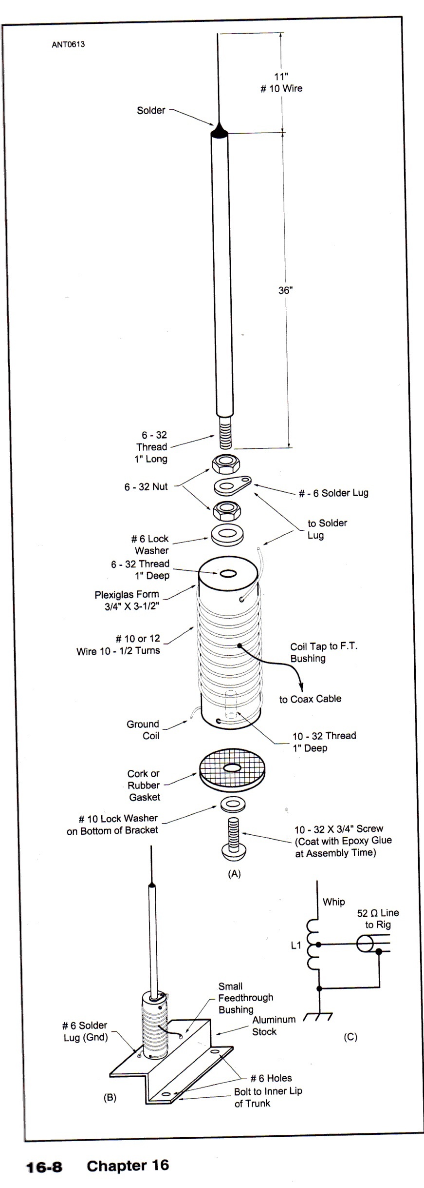
I’ve been using a whip antenna on my backpack mount for APRS while activating. The system works well, but I’m interested in a better antenna. In looking at how mobile antennas work (as a possible alternative) I ran into a stumbling block. The first image below is from the ARRL Antenna Book section on making a 5/8 wave vertical whip for mobile use. My question is, how is that matching network (I’m assuming that’s what it is) at the base of the antenna functioning?
I’m used to seeing ground plane antennas where you might use an inductor to base load the antenna, but with a ground plane you wouldn’t have the whip connected to the ground plane. The electrical diagram in the bottom right of the image indicates that this antenna does have the whip electrically connected to the ground plane. What gives?
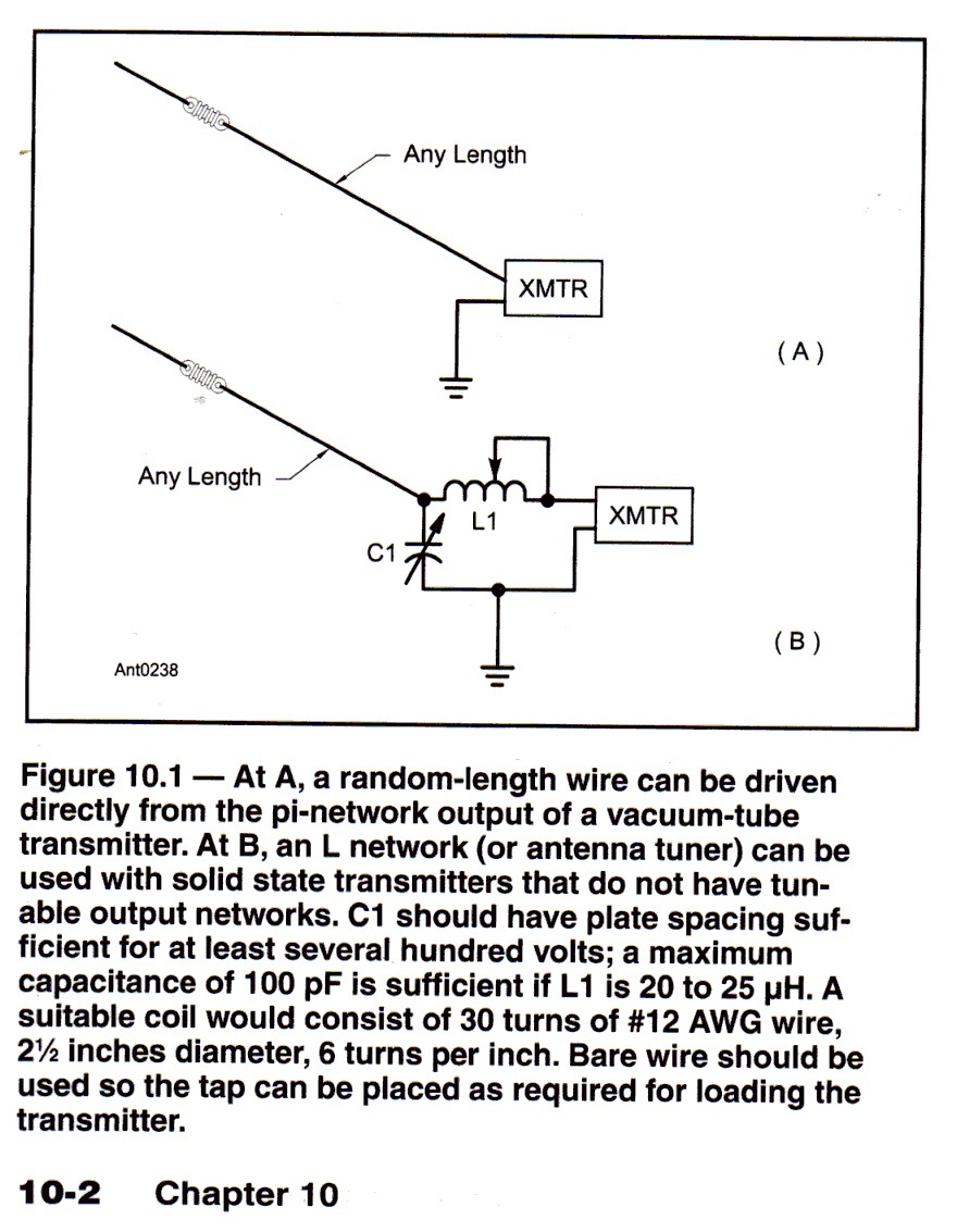
Is the 5/8 wave whip a variation on an end fed antenna? In searching through the Antenna Book I noticed that the electrical diagram for the whip (above) is very similar to the diagram for an end-fed random wire, B below:
Oooh, I know this one as I made a 0.64 wavelength vertical for 10m. (5/8 is 0.625 wavelength)
A 5/8 has an impedance of about 200Ohm (I think, can’t remember but it’s much more than 50Ohm) and a lot of capacitive reactance. To cancel out the capacitance you need a series inductor of the same value, i.e XL + (-XC) = 0 i.e. resistive. Then you feed the antenna at a tapping point on the inductor so it acts as an autotransformer converting the 200Ohm to 50 Ohm.
If you get the inductor value spot on then you cancel out the reactance and the only adjustment is the tap to get 50Ohms. But that can be tedious so the normal way is to add more inductance than you need and a variable capacitor to null out the extra inductive reactance.
On my 10m antenna, the variable capacitor is a piece of RG174 coax about 9cm long. The inner connects to the top of the coil and the screen to earth. The coax is left open at the other end. I originally connect about 12cms and cut back a snip at a time till everything was 50+j0 on the MFJ259. The coil tap connects with a crocodile clip and there is one place for 28.000-28.6 and another for 29.5MHz.
The antenna handbooks indicate that the 0.64 or 5/8 wavelength vertical above a ground plane has the lowest angle of radiation. But at that length it is not resonant and has a reactive feed impedance. This is usually treated by adding series inductance at the base, or some other kind of matching network. the improvement in performance over a 1/4 wave is a few db, if they have an equally good ground plane.
But a 1/4 wave with a decent ground plane (which you need with the 5/8 anyway) works far better than a stubby helical, if that’s where you are starting. The improvement is several S points. i have both types of antenna for my icom HT and the telescoping quarter wave gives far better signals than the helical.
Suggestion: it would be worth trying a 1/4 wave vertical first, before going to a 5/8 which will catch on more trees and other stuff if it’s that kind of hill.
The info you have supplied does not indicate the frequency band. The APRS reference suggests 2m. In that case the “Flowerpot antenna” may be just what you need. See VK2ZOI website. Drop me an Email if you need more detail. G0EVV@hotmail.co.uk
Regards
David
Thanks to everyone; very good feedback from all. Reading the posts gives me a much better understanding of how those antennas work. The connection to ground only works at DC, and the coil cancels out the capacitive reactance. The tap into the coil at the right location matches the impedance to around 50 ohms.
I think I have enough background to start experimenting now. The backpack mount that I’m using is a length of PVC with a female BNC connector epoxied into the top. A short run of RG 174 connects the mount to the radio, allowing me to store the radio anywhere on or in my pack while keeping the antenna up in the air.
After reading through the posts I’m thinking that I could adapt that mount to experiment with all kinds of verticals. I could add rudimentary, short radials by connecting some off-the-shelf springs or short lengths of wire to the mount where the antenna attaches. It wouldn’t be a perfect ground plane, but it should be good enough. With the radials in place I can test out different vertical elements to see what gives me the strongest signals. I can ping a distant repeater to get a repeatable (no pun intended) signal that I can test with.
After some testing I’ll probably be able to come up with a few different options. Some with longer antennas for more signal in clear terrain, and some shorter elements for acceptable signals in wooded or brush-filled terrain. Hmmnn . . . thoughts are churning. I’ll post my results on the reflector after I do some testing.
Thanks again everyone,
Brandon, N6BSC
For a backpack-mounted VHF antenna I would chose a simple design, such as a vertical dipole tied to the outside of the bag, or a quarter wave antenna with the backpack frame as a counterpoise. Any advantage in radiation pattern that may be gained from, say, a 5/8 wavelength antenna may be lost if you aren’t standing straight.
For bands such as 6 m or 10 m (or further down in the spectrum) you might want to consider a shortened vertical (by whatever means are convenient, with an inductor, a capacitive hat, or both), or you’ll keep bumping into door frames, tree branches, telephone wires … unless you are out in the open country.