Although this wasn’t a SOTA-specific project, it should come in handy for those doing VHF activations:
I’ve wanted a way to compare handheld antennas, but the problem is always getting an analyzer hooked up. Also, handheld antennas depend on the radio itself underneath the antenna to provide part of the total “antenna system”.
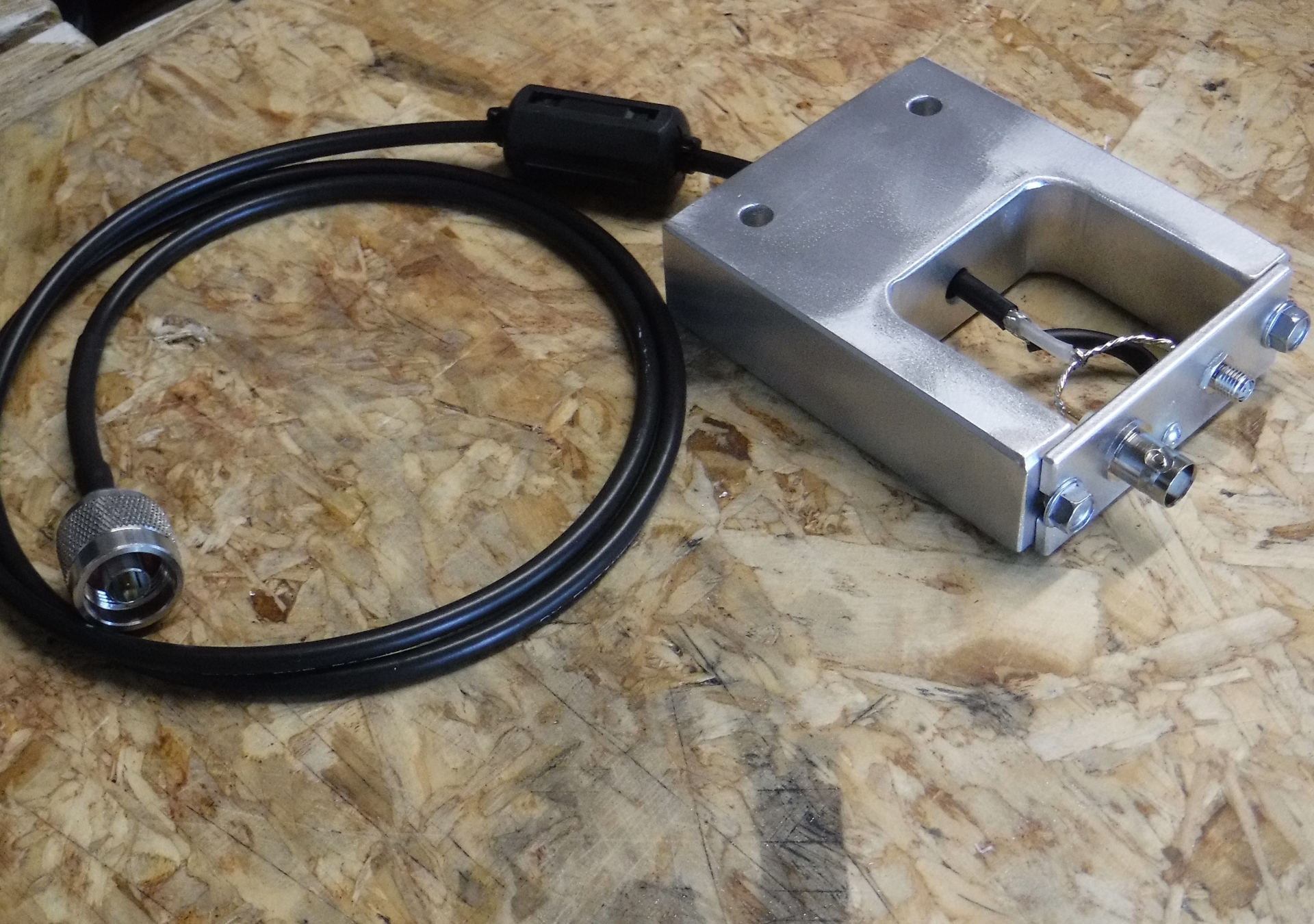
While I was researching handheld antennas I came across an article by Richard Kiefer, K0DK, called “High-Efficiency Antennas for Hand-Held Radios.” In the article he talked about half-wave end fed antennas (good info), but what really grabbed my attention was the testing rig he used. It is basically an Ht imitator with a cable coming out the bottom to hook up to an analyzer. I took the idea and expanded on it a bit, making a radio imitator with both BNC and SMA connectors. Here is a close-up of the tester:
Another view of the fixture. It is just block of 3x1 aluminum stock with the middle cut out. I then mounted connectors into a piece of flat bar on the top, and made the top removable so that it is easy to work on.
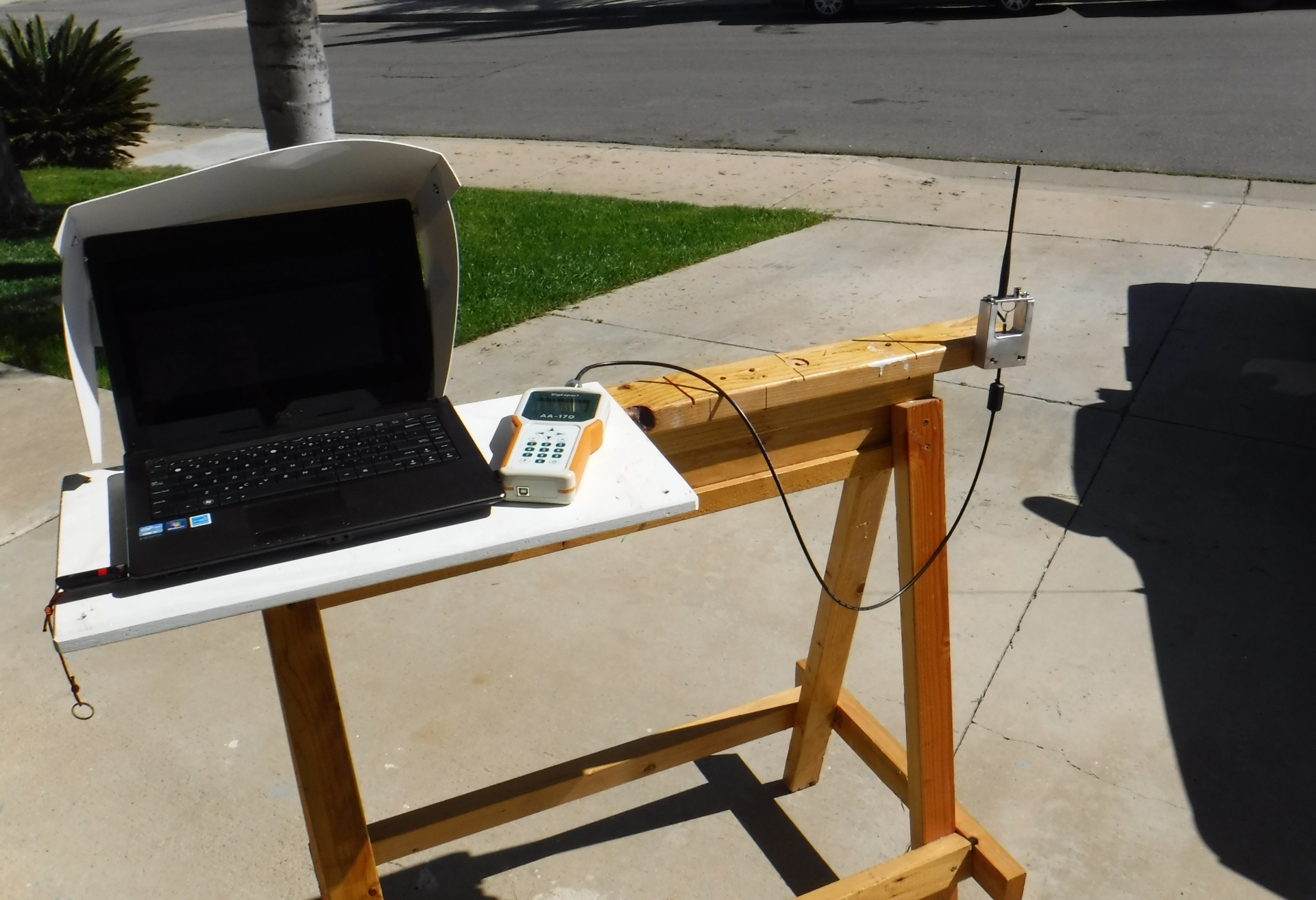
Everything set up and ready for testing. Technically I should probably keep everything further away from the antennas so that I can get a “truer” reading. However, since these antennas are always used in a messy near-field environment I figured that this was good enough.
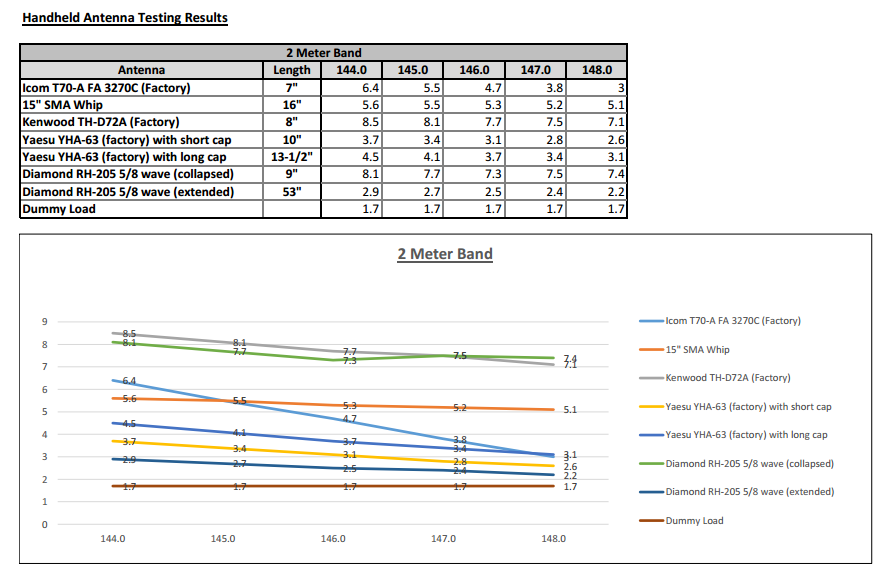
2-Meter band test results shown below. I put everything into an Excel workbook and added a graph to make it easier to visualize the results. Based on the dummy load testing it looks like the fixture is adding 0.7 to the SWR, so these numbers are all probably a bit high. I’ll be doing further testing to confirm.
SWR by itself isn’t everything, but it’s nice to be able to quantify what I can expect from different antennas. One of the ones that I’ve been using a lot lately actually turned out to have the 3rd worst SWR curve out of the bunch! Not going to use that one on 2 M any more.
I think that by substituting a radio for the analyzer I could also measure relative gain - at least in terms of comparative S-units on the same receiver. That’s a project for another day though.
73,
Brandon
However, I think by trying to allow for multiple connector types your fixture is creating an additional impedance in parallel with the one you have on test. Also the unshielded wiring will be allowing radiation to occur from the wiring in the fixture rather than from the antenna.
I suspect a lot of radiation would be occurring within the first few cm (or first inch) of unshielded coax just above the point where the coax shield ends. That’s the effective start of the antenna. The antennas screwed into the socket are extensions to those first few cm of unshielded wire.
To improve it, I’d suggest using a single continuous coaxial cable to the antenna socket. Use BNC/SMA adaptors if necessary to provide the two choices and manually change the feed line to each antenna but only have one antenna option available. Otherwise the unused connector and its feedline are shunting the antenna under test. That will change the impedance of the antenna under test (affecting its measured SWR) and also will radiate energy which will somewhat invalidate comparisons of antennas.
As you say, SWR is only one part of the story, and radiation efficiency is completely different. But both factors can only be measured if the setup does not affect the accuracy or validity of the measurements taken.
The first step in validating the setup would be a perfect dummy load that is known to be a good match on the frequency. And even that is not always easy to find. I have several dummy loads here marked as good to 500 MHz and both are rubbish above 100 MHz.
A very nice idea.and interesting results.
As Andrew says - we are both long time VHF/UHF constructors and operators - the length of unscreened coax to the sockets is a concern. I would either do as Andrew suggests or as a compromise connect a brass or copper strip 1/4 inch wide between the two sockets and connect the centre coax to the centre of that and the braid to the top plate with minimal lengths. A piece of pcb could be used if brass or copper strip is hard to come by. The idea is the keep the impedance low, preferably near to 50 ohms and to minimise parallel impedances.
My guess is that the SWR of the antenna might go up and that of the load go down. I have found two 100 ohm half watt resistors fitted in parallel into a coax plug with minimal lead length makes an OK load on 2 m.
Good ideas from both- thanks for the feedback. I think you guys are probably correct. With as short as these wavelengths are there could indeed be issues with the way the coax is connected. I could imagine that since the Ht antennas I’m testing are electrically short anyway it would magnify any issues with the coax connection.
I’ll try connecting the coax to only the BNC connector, and then see what I get from my dummy load. If the SWR drops to 1:1 then I’ll know that it was the way the dual connectors were attached that was causing an issue.
If that is successful, then I’ll experiment with other ways to get both connectors attached. If I can come up with something that would allow both to be present that would be great, but if not I can always just use adapters to test different antennas, as was suggested.
Thanks,
Brandon
It is amazing how little departure from a direct connection you can make, to invalidate results. In one test I read, a HF balun was tested with some leads going from the balun to a dummy load. When the inductance of the leads was calculated, it was 0.5 uH which was enough to totally ruin any SWR measurements being made to “validate” the balun.
For your 2m test, I suggest the longest unshielded wire should be about the length of the BNC connector that sticks out of the chassis. Any extra length is substantial at that wavelength. Multiply it by 40 and consider measuring an 80m antenna with that amount of hookup wire between the end of the coax and the dummy load. It’s only when you do that, that the significance of 4cm of unshielded wire at 144 MHz becomes apparent. Estimated length of 4cm x 40 = 160cm, or about 5 feet. You’d never do that! (40 because 80m is 40 times 2m)
Another way to assess it is to consider how much lead length you’d use on 80m without concern. Maybe 5 or 6 inches? Divide by 40. That’s 1/8" for 2m. Ie. the length of the bit on the end of the socket where you solder your wires. The coax shield should end within a fraction of an inch from that point. Like, a few 1/100ths of an inch.
Anyway as I remarked earlier I really like the idea and hope you get some results that look more encouraging than the extremely high SWR readings seen earlier. Measurements and comparisons are always informative. Sometimes they tell us things we don’t want to know! Our favourite antennas can turn out to be duds.
An interesting experiment, which has also teased out a few more thoughts and ideas.
I wonder if you have tried connecting the antennas directly on to the analyser?
In the photo, it appears to be somewhat similar to a handheld in size.
That would cut out the coax connection at the test jig, and also the trailing coax lead which might be acting as a counterpoise - though it looks as though you have a choke on that, which probably helps.