15 Watt EIRP - What does that mean?

Hi Hans,

Thanks for the insight. 60/4 = 15. I can do that. 50 w to a dipole would apparently comply. I presume the vertical radiation is discounted.

We in VK are required to calculate EMR exposure limits so as to keep the public safe so antenna pattern and ERP part of the deal. There is an alternative simpler “safe” calculation we can do.

Our problem is getting some clear frequencies as the 5 to 5.5 MHz range is fully allocated although I believe a couple of channels are no longer in use. Our licencing authority has bigger fish to fry so not hopeful about an allocation for 60 m this year.

When (if) we get the band running 10 W SSB/CW/digital should be acceptable if the antenna as comparable to a dipole in gain and pattern and maybe 50 W with an appropriate analysis.

73
Ron
VK3AFW

I am not sure, Ron
IF the mentioned 6dB loss of a “low” dipole is to understand as overall loss (and therefore would be allowed for direct/correct comparison with an isotropic radiator),
OR as loss of the main lobe only?

BTW, This paper may be of common interest, have fun:
https://home.zhaw.ch/kunr/NTM1/literatur/Rhode_Schwarz_Antenna_Basics.pdf

Heinz HB9BCB

Thanks again Hans.

This 15 W eirp is a bit awkward for SOTA and HF. Free space calcs while straight forward are unlikely to apply in the field.

Just to get a better feel for the situation for SOTA activations here in VK I ran a simulation for a 5.3 MHz dipole in inverted vee form. The apex was at 9 m and the ends at 3 m - to be safe for the public. Now of course the results depend directly on the ground conditions, so I would need to spend an hour or so running different possibilities. With the default “medium” ground the maximum gain of the dipole is 7.5 dBi straight up. Fortunately this hardly changes for very conductive ground. For radiation angles of less that 20 to 22 degrees the antenna has less gain than an isotropic radiator. For the higher angles when NVI might come into play then the dipole has gain over an isotropic radiator, typically 5 dBi. Let’s assume 6 dBi to have a little margin and to capture all usable takeoff angles.

If the regulator says 15 W eirp and nothing about radiation patterns then 10 W on a mountain rock knife edge could scrape in if the dipole only achieves 2.2 dBi.

6dB is near enough to a factor of 4. So 15/4 or 3.75 W is as much as I can run if the ground is flat and significantly conductive and line losses are low. It is assumed as stated above that NVI is used.

I could run 5 W if the antenna, feedline and matching system had 1.25 dB loss, which would not be unreasonable estimate…

A possible answer to the question posed by this thread started by HB9BCB. A Rule of Thumb.

If you have a 15 W eirp limit and use a low dipole then 5 w rf from the tx is as much as you can run for a practical SOTA set-up.

If you are pedantic then a Rule of Thumb will never suit and you need to do your own analysis. My 6 dB number etc can be debated for months if the assumptions are varied. If the regulator is helpful and reasonable a 10 W output limit and no gain over a dipole would be helpful adjuncts to defining a practical 15 W eirp compliance for all stations.

73
Ron
VK3AFW

1 Like

Hi Ed,

the isotropic radiator is a theoretical concept for an antenna that is 100% efficient, sits in free space and radiates equally in all directions. It is used as a reference, to express performance of another antenna.

The decibel (dB) expresses a ratio between two values and it is dimensionless. However, dBi, dBm, dBc and other are not ratios but dimensions, that say how many times bigger or smaller a unit is compared to another. For example, 13dB means a certain power value is 20 times bigger than another, but 13dBm says “20 times bigger than 1mW”, which equates to 20mW.

It’s the same with antenna gain: 3dB means just 2 times bigger, but 3dBi means 2 times bigger (or stronger field generated) than the theoretical isotropic radiator.

You might ask yourself, “how can a dipole generate a stronger electromagnetic field than an isotropic radiator, when they are taking the same electric power input ?”. The trick to understanding antenna gain is that the overall field is not stronger, but it’s more concentrated in a certain direction. So, while overall a dipole and an isotropic radiator would put out the same energy, the isotropic radiator sends it evenly in all directions while the dipole concentrates it in the plane perpendicular to it’s axis. Mathematics has concluded that in this plane, the dipole generates a field 1.64 times (2.15dB) stronger than the isotropic radiator, therefore the dipole has a 2.15dBi gain. This happens at the expense of energy radiated along it’s axis.

But, this is in free space. As soon as you get close to any other objects, the dipole’s radiation pattern is distorted, forcing it to concentrate even more energy on certain directions and losing on others. Add another dipole of similar length close to your radiating dipole and parallel to it, you’ll see a huge shift in radiation pattern, with most energy going in just one direction. This is called an Yagi antenna :).

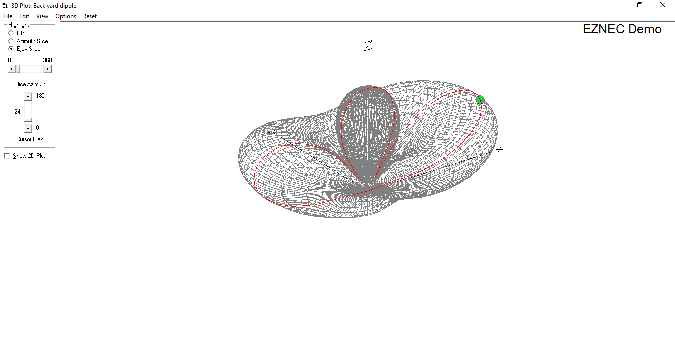
However, the biggest influence in radiation pattern comes from the most significant object close to your antenna, Planet Earth. It will force all the energy that was going to an entire plane 360 degrees around the free space dipole in just two narrow lobes. Depending on antenna height/position and the Earth’s conductivity & dielectric constant near your antenna, the lobes can be narrow enough that field strength on the best direction is almost 8 times (9dB) stronger that what the isotrope radiator would generate. It’s like a baloon that you squeeze, press on one side and it will expand towards another.

TL;DR - isotropic radiator spreads energy evenly, free space dipole concentrates energy in one plane, dipole close to Earth concentrates the same energy in just two lobes.

Razvan M0HZH / YO9IRF

My rule of thumb would be to run enough power to give a good signal strength but not too much that it attracts the attention of the regulators.

3 Likes

Thanks for the very detailed explanation Razan, but to bring this topic (hopefully) back to the original question - how much is 15w EIRP. In a practical way for “mere mortals”?

Since in most cases (certainly when activating), the most common antenna is likely to be a dipole in an inverted-V configuration on a 5 7 or 10m fibreglass mast. How much would be too much power (assuming 1.5dB loss in coax/connectors).

It’d be good to have a “rule of thumb” figure for the maximum allowed output power setting on a rig not to exceed 15w EIRP from the antenna. We can alwys run less than this to make sure we are on the correct side of the regulations.

73 Ed.

2W

Hmm, certainly wont need the small amp on 60m then!!

Of course not. I’ve got thousands of 60m SSB SOTA QSOs under my belt with an FT817 that produces 4.5W.

Of course UK operators are allowed 200w EIRP on 60m, so it’s less of an issue, but it’s looking like barefoot FT817 set at one power level down from maximum - i.e. documented as 2.5w out but actually somewhere between 2 and 2.5w. I have worked into VK with just 2.5w SSB from a DL summit before, it all depends upon propagation and that’ll be the fun, to find out what is possible on 60m on the 29th. - Just hope the weather warms up a little, otherwise temperature rather than battery capacity is going to be the limiting factor as to how long I can stay on the summit.

Ed.

Hi Ed,

my guess is even 5W from the transmitter is safe. Dipole reaches 9dBi at 0.6wl above seawater, with the typical SOTA installation 0.1-0.2wl above rocky ground I wouldn’t expect more than ~5dBi.

Razvan.

Ah, but… what about the gain you might get from mounting your dipole above a wire fence. :slight_smile:

And then the gain is only relevant in the direction the signal is being monitored from by the authorities …:grin:

How will the authorities measure EIRP to ensure conformity?

Do the authorities understand the difference between ERP and EIRP ??

Lots of questions ! I think as long as we make a good attempt at meeting the QRPP power limit, no one is going to be too worried…

Ed.

More than most amateurs do.

EIRP to any direction must stay below the limit :).

It is almost impossible to accurately measure EIRP outside a lab, because you can’t isolate just the signal coming directly from one source. Authorities generally use formulas that take into account antenna type, height and transmitter power. And even if, they won’t follow you to the summit with equipment 10x heavier than yours just to take field measurements while you activate SOTA.

I guess you just need to do what you feel is right.

Razvan,

Hi All,

Razvan is right.

The asked for Rule of Thumb answers have been given several times but if read were not understood by some, or maybe they don’t like the answers. So try this format:

5 w to a 60 m half wave dipole, probability of not exceeding 15 W EIRP, 70%
2.5 W to a 60 m half wave dipole, probability of not exceeding 15 W EIRP, 100%.

The probability is based on the range of known unknowns re height and ground and outlook, feed line losses and such. The more you can define the better you can determine the levels and the probability.

The authorities have their own methods of determining and enforcing compliance. For SOTA it’s our own conscience that determines what we do. I could run 100 W but that would not meet the either the rules or spirit of SOTA so it’s not on my agenda. I would be cheating on myself as much as on other SOTA people or the VK ACMA.

One more time, 5 W is the maximum power for 15 W EIRP when using a dipole and in some situations you might exceed the 15 W EIRP.

Your call. YMMV.

73
Ron
VK3AFW

Well put, Ron. I can only add that 5 watts and a less than half wave doublet and tuner will give more of a cushion. One might ask why use a less than optimum antenna, but not all summits are roomy - and a couple of times I have inadvertantly used a 20 metre OCF dipole and 5 watts to successfully chase an activation (where my tuner is, the antenna selector has a lot of parallax!) Oh, and when I have the antenna selector right I am currently using a 20 metre long wire, quite successfully.

It cannot be overemphasised that during the daytime, for distances of up to several hundred kilometres 5 megs will be either dead or much more often VERY co-operative!

Brian

Thanks Ron et al. for the detailed analysis and synthesis/rule of thumb!

Nothing to add but that this is especially to consider also by the chasers - with usually respectable antennas and/or not be able to reduce the transmission power accordingly (technically or mentally …). :wink:

73, Heinz HB9BCB
• • • - • -

Or at least, those chasers constrained by WRC-15 rules - many are not.

No but you’re still constrained by an EIRP limit, Brian.